Filament Runout Detection on Reprapf Firmware 3 (RRF3)
-
Hey guys,
I have a problem with setting up Filament Runout Detection on RRF3. I use this code:
M591 P3 C"e1_stop" S1
Or M591 D1 P3 C"e1_stop" S1
Or M591 D0 P3 C"e1_stop" S1The Filament Runout Sensor is a simple mechanical switch connected to the E1 Endstop. But using that it does not work. Meaning the endstop only says triggerd-no under the machine specific tab.
The switchis not defectiv. The light while triggerd and not triggerd works. If I connect my filament-switch to (i.e.) the z-axis-Endstop input it works.Here you can see my complete config (at the moment filament ronout is commented out):
; Configuration file for Duet WiFi (firmware version 3)
; executed by the firmware on start-up
;
; generated by RepRapFirmware Configuration Tool v2.1.4 on Thu Jan 02 2020 13:27:54 GMT+0100 (Mitteleuropäische Normalzeit)

; General preferences
G90                                                    ; send absolute coordinates...
M83                                                    ; ...but relative extruder moves
M550 P"CR-3D C1"                                       ; set printer name

M667 S1                                                ; select CoreXY mode

; Network
M552 S1                                                ; enable network
M586 P0 S1                                             ; enable HTTP
M586 P1 S0                                             ; disable FTP
M586 P2 S0                                             ; disable Telnet

; Drives
M569 P0 S0                                             ; physical drive 0 for x goes forwards
M569 P1 S0                                             ; physical drive 1 for y goes forwards
M569 P2 S0                                             ; physical drive 2 for z goes forwards
M569 P3 S0                                             ; physical drive 3 for coupler on E0 goes forwards
M569 P4 S0                                             ; physical drive 4 for E1 goes forwards
M569 P5 S0                                             ; physical drive 5 for E2 goes forwards
M584 X0 Y1 Z2 C3 E4:5                                  ; set drive mapping
M350 X16 Y16 Z16 C16 E16:16 I1                         ; configure microstepping with interpolation
M92 X80 Y80 Z1600 E409:415                             ; set steps per mm
M566 X300 Y300 Z12 E600                                ; set maximum instantaneous speed changes (mm/min)
M203 X12000 Y12000 Z900 E1500                          ; set maximum speeds (mm/min)
M201 X1200 Y1200 Z600 C600 E500:500                    ; set accelerations (mm/s^2)
M906 X1500 Y1500 Z1400 C800 E800:800 I30              ; set motor currents (mA) and motor idle factor in per cent
M84 S30                                                ; set idle timeout

; Axis Limits
M208 X0:300 Y-40:256 Z-10.8:310 C0:400             ; set axis limits

; Endstops
M574 X2 S1 P"xstop"                                    ; configure active-high endstop for high end on X via pin xstop
M574 Y2 S1 P"!ystop"                                   ; configure active-low endstop for high end on Y via pin ystop
M574 C1 S1 P"e0stop"                                   ; configure active-high endstop for low end on C via pin E0stop

; Z-Probe
M558 P5 C"zstop" H5 F120 T12000                        ; set Z probe type to switch and the dive height + speeds
G31 P500 X0 Y35 Z2.5                                   ; set Z probe trigger value, offset and trigger height
M557 X45:275 Y5:235 S45                                ; define mesh grid

; Temperature Sensor & Heaters

M308 S0 P"bedtemp" Y"thermistor" T100000 B4092         ; configure sensor 0 as thermistor on pin bedtemp
M308 S1 P"e0temp" Y"thermistor" T100000 B4725 C7.06e-8 ; configure sensor 1 as thermistor on pin e0temp
;M308 S2 P"e1temp" Y"thermistor" T100000 B4725 C7.06e-8 ; configure sensor 2 as thermistor on pin e1temp
;M308 S3 P"e2temp" Y"thermistor" T100000 B4092 S"Chamber"; configure sensor 3 as thermistor on pin e2temp (DUEX)

; Heaters
M950 H0 C"bedheat" T0                                  ; create bed heater output on bedheat and map it to sensor 0
M143 H0 S120                                           ; set temperature limit for heater 0 to 120C
M307 H0 B0 S1.00  				       ; disable bang-bang mode for the nozzle heater and set PWM limit
M950 H1 C"e0heat" T1                                   ; create nozzle heater output on e0heat and map it to sensor 1
M143 H1 S280                                           ; set temperature limit for heater 1 to 280C
M307 H1 B0 S1.00                                       ; disable bang-bang mode for the nozzle heater and set PWM limit
;M950 H2 C"e1heat" T2                                   ; create nozzle heater output on e0heat and map it to sensor 2
;M143 H2 S255                                           ; set temperature limit for heater 1 to 280C
;M307 H2 B0 S1.00                                       ; disable bang-bang mode for the nozzle heater and set PWM limit

; Fans
M950 F0 C"fan0" Q500                                   ; part cooling T0 - create fan 0 on pin fan0 and set its frequency
M106 P0 S0 H-1                                         ; part cooling T0 - set fan 0 value. Thermostatic control is turned off
M950 F1 C"fan1" Q500                                   ; LED - create fan 1 on pin fan1 and set its frequency
M106 P1 S0 H-1                                         ; LED - set fan 1 value. Thermostatic control is turned on
M950 F2 C"fan2" Q500                                   ; coldend T0 - create fan 2 on pin fan2 and set its frequency
M106 P2 S1 H1 T45                                      ; coldend T0 - set fan 2 value. Thermostatic control is turned on
;M950 F3 C"duex.fan3" Q500                              ; coldend T1 - create fan 3 on pin fan3 and set its frequency
;M106 P3 S1 H2 T45                                      ; coldend T1 - set fan 3 value. Thermostatic control is turned on
M950 F4 C"duex.fan4" Q500                              ; part cooling T1 - create fan 4 on pin fan4 and set its frequency
M106 P4 S0 H-1                                         ; part cooling T1 - set fan 4 value. Thermostatic control is turned on
M950 F5 C"duex.fan5" Q500                              ; chamber - create fan 5 on pin fan45 and set its frequency
M106 P5 S1 H2 T45                                      ; chamber - set fan 5 value. Thermostatic control is turned on

; Tool 0
M563 P0 S"Hemera" D0 H1 F4                             ; define tool 0
G10 P0 X0 Y0 Z0                                        ; set tool 0 axis offsets
G10 P0 R0 S0                                           ; set initial tool 0 active and standby temperatures to 0C

; Tool 1
;M563 P1 S"BigBooster" D1 H2 F04                        ; define tool 1
;G10 P1 X0 Y0 Z0                                        ; set tool 1 axis offsets
;G10 P1 R0 S0                                           ; set initial tool 1 in-active and standby temperatures to 0C


; Filament Runout
;M591 P3 C"e1_stop" S1
;M591 D0 P1 C"e1_stop" S1
;M591 D1 P1 C4 S1
;M591 D2 P2 C5 S1

; Custom settings are not defined

; Miscellaneous
M501                                                   ; load saved parameters from non-volatile memory
T0
On another point:on the machine specific tab alway 5 endstops (0 to 4) are listed. Although 4 is not configured at the moment. Additionally I have a duex 5 connected. Why is it not showing up?
Thanks for your help,
Max -
Are you aware that filament sensors are only active while printing from SD card?
-
Thanks for your Help.
I an aware of that. But does that mean I can Not Test it while the Machine is Not printing?
I thought that means that only the Pause is triggered during printing. Is that assumption wrong?Greets
Max -
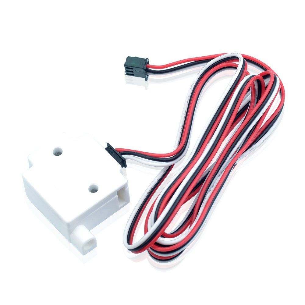
Se mi posso permettere dato che l'ho appena risolto il problema che anche tu hai, ho un sensore meccanico tipo quello in foto e per me la configurazione ha funzionato, l'ho messo nel finecorsa di E1.
M591 D0 P2 C"e0_stop" S1 , lo metti fondo al config, una volta salvato in console fai M591 D0 e ti dice se funziona o meno.runout.jpg -
@MacNite said in Filament Runout Detection on Reprapf Firmware 3 (RRF3):
Thanks for your Help.
I an aware of that. But does that mean I can Not Test it while the Machine is Not printing?
I thought that means that only the Pause is triggered during printing. Is that assumption wrong?To test it, send M591 D# where # is the extruder drive number. It will report the status. In RRF 3.01 you can also retrieve the status via the object model.
-
Thanks David and Leblond.
I feel so stupid I did not see this...works perfectly fine now!
Greets ,
have a nice weekend and stay safe.
Max