Quick question about boot order with an RPi and Duet 3
-
@bearer Thanks for the links. tl:dr but they seem to be related to powering the RPI from the Duet or vice versa, or powering over USB. But in my case, I have a completely separate 5V supply. The gnd side of all DC supplies are connected together and also connected to chassis earth. There is only one connection to mains and the earth side of that too is connected to chassis earth. Not my field of expertise by any means but I don't think there is much likelhood of ground loops? Yes? No?.
-
@deckingman said in Quick question about boot order with an RPi and Duet 3:
@bearer Thanks for the links. tl:dr but they seem to be related to powering the RPI from the Duet or vice versa, or powering over USB. But in my case, I have a completely separate 5V supply. The gnd side of all DC supplies are connected together and also connected to chassis earth. There is only one connection to mains and the earth side of that too is connected to chassis earth. Not my field of expertise by any means but I don't think there is much likelhood of ground loops? Yes? No?.
the point dc42 made was having a powered rPi with a unpowered Duet could theoretically cause damage to the rPi's SPI circutry.
the link to the isolator was a proposed solution to remedy that - getting full galvanic isolation as a side effect.
(but you'd still run the risk of ground loops with your setup IF say the 5v GND connection were to get interrupted; as is the case with all ground loops, they're contingent on a fault)
-
@DocTrucker said in Quick question about boot order with an RPi and Duet 3:
@deckingman .............. I know wiring heaters in series isn't a great move but what about pairing up the fans and running from 24V?......................
Ohh man. I did that - with the exception of wiring the fans in series
 . That is to say, I forgot to move a jumper on one of expansion boards and put 24V on two expensive, near silent, Sunon Maglev fans. They didn't even attempt to turn - just gave a discrete "pop". Still waiting for the replacements to arrive..........
 -
@bearer said in Quick question about boot order with an RPi and Duet 3:
the point dc42 made was having a powered rPi with a unpowered Duet could theoretically cause damage to the rPi's SPI circutry.
the link to the isolator was a proposed solution to remedy that - getting full galvanic isolation as a side effect.
Ahh, OK. Thanks. Sounds like that's best avoided then...
-
@deckingman said in Quick question about boot order with an RPi and Duet 3:
Sounds like that's best avoided then...
It is easily avoided by powering both from the same (5v) supply through the ribbon cable; direction doesn't matter, both will always be powered together. (just make sure to set the jumpers correctly)
I had other reasons for wanting to try full isolation.
-
If the pi and the duet are both powered from an external 5V supply then no problem? In this instance I think I'd be inclinded to have a single posative feed to the pi, let it ground through the ribbon, and disconnect the posative feed to the pi via the ribbon. You get past the 3A limit to the pi problem then. And no ground loops.
I'd need to recheck the schematics for the Duet3 but on the Duet2, v0.8.5, and v0.6 all ground terminals were connected on the boards. With that in mind the easiest way to deal with multiple PSUs is to chain the negatives on the PSUs and only connect one negative to each control board with a big thick wire of a higher rating than the PSU can kick out before dropping to short circuit protection. For the seperate supplies take the posatives to the board.
What I'd need to look at further is how ground loops are avoided with the ancillary boards. Could you end up with a fault current going down the CAN control wire, or are they isolated?
Running 3 P3Steel with Duet 2. Duet 3 on the shelf looking for a suitable machine. One first generation Duet in a Logo/Turtle style robot!
-
The issue with an unpowered Duet and a powered Pi is only if the Duet's USB is connected to a Pi USB. In normal operation, you don't need that connection. I have them connected via a USB cable that has the power wires cut so only data flows and only because I've been testing RRF and DSF releases. I've been running for 8 months now with leaving the SBC powered on and powering the Duet on and off with absolutely no issues.
There has been a recent change in the behavior of things when the Duet is reset. Until recently, if you reset the Duet either by M999 or by hard reset on the Duet, it would read config.g and restart just as quickly as if it were in standalone mode. The recent change on the SBC side was to also restart the DuetControlServer to resolve any "sync" issues. This can add 5 seconds to the restart time. You can disable the new behavior in the DCS's config.json file however.
-
@DocTrucker said in Quick question about boot order with an RPi and Duet 3:
You get past the 3A limit to the pi problem then.
is the problem real? i mean micro usb which is the (normal) alternative is rated for mere 1.8A even if Raspberry Pi supplies
But yes, you could split the power pins out of the Ribbon cable and power the boards from the same ext 5v supply. Dealers choice on using the SBC header or 5V_EXT header to power the Duet I guess.
CAN bus isn't necessarily isolated, but its also not necessarily ground referenced so I don't think I'll comment more on that
-
Can we go back to 24 seconds? (By the way, I get that same time, roughly). Is this a real problem?
Data point 1: The cooling fan on the smart effector in my delta causes false triggers of the probe. I turn that fan off while probing. At the beginning of every print job. And, yes, the hotend is hot (for accurate probing) and has filament in it. For much longer than 24 seconds. No issues, ever.
The finned heat sink in most hot ends is physically large enough to have some amount of thermal inertia. I'd seriously doubt that its temperature changes more than a trivial amount with the fan off for 20 or 30 seconds.
Is there some hot end config or use case that I'm missing?
Yes? No? Thoughts?
Delta / Kossel printer fanatic
-
@bearer said in Quick question about boot order with an RPi and Duet 3:
It is easily avoided by powering both from the same (5v) supply through the ribbon cable; direction doesn't matter, both will always be powered together. (just make sure to set the jumpers correctly)
Sorry I'm being especially thick today. To be clear, I connect the RPI to the Duet with the ribbon cable. Then I could connect my existing 5V to the Duet Ext 5V connector, remove the internal 5V enable jumper, fit a jumper to 5V to SBC and remove the SBC to 5V jumper yes?
-
@deckingman said in Quick question about boot order with an RPi and Duet 3:
Sorry I'm being especially thick today. To be clear, I connect the RPI to the Duet with the ribbon cable. Then I could connect my existing 5V to the Duet Ext 5V connector, remove the internal 5V enable jumper, fit a jumper to 5V to SBC a
nd remove the SBC to 5V jumper yes?only remove the internal 5v jumper (and fit the 5v to SBC), was a typo in the docs (was only recently corrected by dc42)
-
@Danal said in Quick question about boot order with an RPi and Duet 3:
Is there some hot end config or use case that I'm missing?
Yes? No? Thoughts?
Yes. See the scenario in my very first post.
-
@deckingman said in Quick question about boot order with an RPi and Duet 3:
Slice Engineering Mosquito style
Got it, I will take a look at those. Thanks for clarifying!
While the conversations about what Duet should do continue... have you considered a small external circuit, just a FET or something, switching logic from the duet and powered directly from whatever fan V, the goal being to invert the logic of controlling those fans at the hardware level? And then invert the output pin on the Duet (via config).
This should result that they would come on at power up, and only after the Duet is fully up would they be switched on and off per what the Duet thinks is right.
Again, this is not a 'strategic' fix... but given your situation, it might be worth the 'hack', for now.
-
@Danal Yes, the Mosquito heat breaks have extremely low thermal mass. The cross sectional area is in the order of 15% of say an E3D V6 where the heat break is also a structural element. Which makes them extremely efficient as heat breaks and as I mentioned above, one can print PLA all day long with no fan and even without the tiny copper heat sink providing the filament is constantly moving forward (albeit slowly). The problem arises when the filament is static because heat will creep up through the filament itself even though the thermal transfer via the thin wall stainless steel tubes is minimal. That's when the fan is needed.
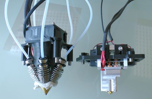
By way of comparison, here is picture of my 6 input hot end assembly on the right next to a Diamond 5 colour on the left. The heat breaks/heat sinks on the Diamond are modified V6 lite (the big finned sliver bits) and the heat break assemblies on mine are the small copper parts which you can just make out if you peer closely.
Ref the fan(s) - I think I'll just wire them as always on as I described above. I destroyed the originals by feeding them 24V but replacements are on the way, and they are almost silent (to my aged ears). Even the high flow versions that I'm currently using aren't too bad.
-
Did you comment on where the fan(s) are connected? Curious if this is different for the toolboard vs the expansion and main board.
-
@bearer said in Quick question about boot order with an RPi and Duet 3:
Did you comment on where the fan(s) are connected? Curious if this is different for the toolboard vs the expansion and main board.
I didn't - but they are (currently) just connected to
io6OUT6 on one of the expansion boards (I think it's 6 - the first 2 pin header).Edit - I meant out6 not io6 - just corrected
-
@deckingman said in Quick question about boot order with an RPi and Duet 3:
@bearer said in Quick question about boot order with an RPi and Duet 3:
Did you comment on where the fan(s) are connected? Curious if this is different for the toolboard vs the expansion and main board.
I didn't - but they are (currently) just connected to io6 on one of the expansion boards (I think it's 6 - the first 2 pin header).
Thanks, if you have a toolboard I'd love to see if its different. (both expansion and main board have the pull downs (on all outputs), while the tool board does not). Just a curiosity on my end, so don't put much effort in it on my behalf.
-
@bearer said in Quick question about boot order with an RPi and Duet 3:
@deckingman said in Quick question about boot order with an RPi and Duet 3:
@bearer said in Quick question about boot order with an RPi and Duet 3:
Did you comment on where the fan(s) are connected? Curious if this is different for the toolboard vs the expansion and main board.
I didn't - but they are (currently) just connected to io6 on one of the expansion boards (I think it's 6 - the first 2 pin header).
Thanks, if you have a toolboard I'd love to see if its different. (both expansion and main board have the pull downs, while the tool board does not). Just a curiosity on my end, so don't put much effort in it on my behalf.
Sorry - don't have any tool boards. Also see my edited post above (OUT6 not io6).
-
fair enough! which out it is makes little difference, they're driven the same way all of them.
maybe some of the other users who do have a toolboard can chime in if the behavior is the same as it would be interesting to factor in when people ask if they should get this or that.
-
@bearer The only reason I used OUT6 is that these are simple 2 wire fans and the lower numbered OUT headers are 4 pin with additional gnd and tacho. So I wanted to keep these headers in reserve in case I ever need to add a tacho fan.