Heater setup RRF3.1.1
-
I've just about finish setting up my heaters but ran into an issue which is confusing me. This is the config.g layout below:
; Heater names are !bedheat (H0), !e0heat(H1),!e1heat(H2),!duex.e2heat(H3),!duex.e3heat(H4),!duex.e4heat(H5),!duex.e5heat(H6),duex.e6heat(H7)
; Temperature sensors are bedtemp(T0,S0), e0temp(T1,S1),!e1temp(T2,S2),!duex.e2temp(T3,S3),!duex.e3temp(T4,S4),!duex.e4temp(T5,S5),!duex.e5temp(T6,S6),duex.e6temp(T7,S7)
;BED HEATER 0
M140 H0 ; Heater 0 is the Bed Heater
M308 S0 P"!bed_temp" Y"Thermistor" T100000 B3950 R4700 A"Bed Heater" ; Create bed thermistor sensor + ADC parameters for heater 0
M950 H0 C"bedheat" T0 ; Assign Heater 0 and associate it temperature sensor 0
M143 H0 S150 ; Set temperature limit for heater 0 to 150C
M307 H0 B0 S1.00 ; Disable bang-bang mode for the bed heater and set PWM limit
;
;CHAMBER HEATER 5
M141 H2 ; Heater 2 is chamber heater.
M308 S2 P"!e1_temp" Y"Thermistor" T100000 B3950 R4138 A"Chamber" ; Create chamber thermistor + ADC parameters for heater 2 which is connected to sensor 4 channel
M950 H2 C"duex.e4heat" T2 ; Assign Heater 5 and associate it temperature sensor 4 on the duex5 board.
M143 H2 S100 ; Set temperature limit for heater 2 (E1) to 100C
M307 H2 B0 S1.00 ; Disable bang-bang mode for the chamber heater and set PWM limit
;
;EXTRUDER HEATER 1
M591 S1 P1 C"!e0_stop" ; Use endstop 3 for the filament sensors for drives 0.
M308 S1 P"!e0_temp" Y"Thermistor" T4606017 B5848 C5.548428E-8 R4700 A"Dyze Hotend" ; Create thermistor sensor + ADC parameters for heater 1 (E0)
M950 H1 F0:1 C"e0heat" Q100 T1 ; Assign Heater 1 and associate it with F0 & F1, pwm at 100Hz. Associate it with temperature sensor 1
M143 H1 S490 ; Set temperature limit for heater 1 (E0) to 490C
M307 H1 A659 C363.6 D14.3 S0.50 ; Heater 1 (E0) process parameter for 24V system
M563 P0 S"Dyze Hotend" D0 H1 F0:1 ; Define tool 1
G10 P0 X39 Y20 Z0 ; Set tool 1 axis offsets
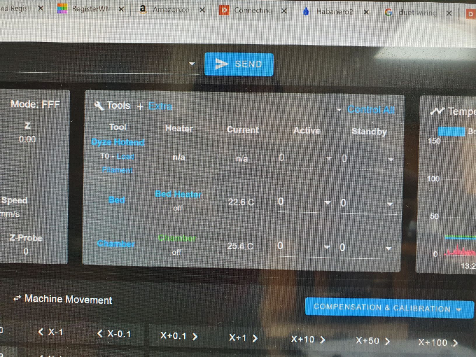
G10 P0 R0 S0 ; Set initial tool 1 active and standby temperatures to 0CWhen I go back onto the dashboard of the web control, I can see the bed and chambers heaters are configured properly. However the bed and current temperature are displayed as n/a

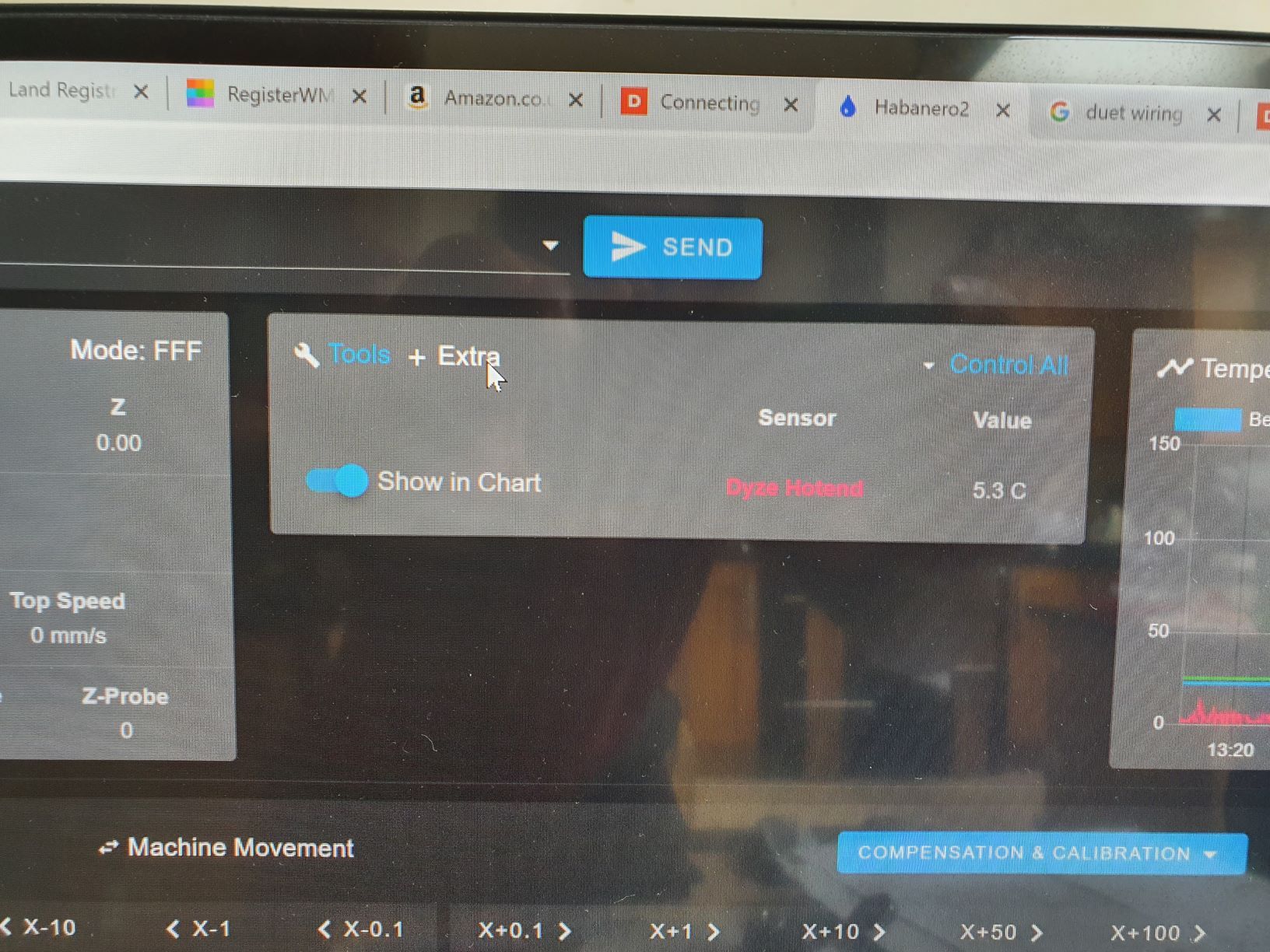
When I click on "extra" I can see the hotend temperature value. Is this how it's meant to appear?

Also, I have loaded filament through the filament sensor but its still saying load filament for Tool 0. On the filament sensor the red indicator light is also on but the board is not recognising that filament has been loaded.
I would really appreciate some assistance on this. Many thanks in advance.
-
How did you generate this config? It looks like you've chosen inverted heaters for some reason?
The load filament text isn't an indication from the filament sensor that filament is or is not loaded. It's a button that will allow you to use the web controls filament load macro function.
https://duet3d.dozuki.com/Wiki/Duet_Web_Control_Manual#Section_Filaments
https://duet3d.dozuki.com/Wiki/Filaments -
The inversion was me trying different things to solve the issue. Removing the exclamation marks from the heaters didn't solved the issue either. I still can't actively use the hotend. I've tried so many things I've now run out of options. Please see my entire config.g file below. I am still in the testing phase and have only managed to get to the heaters which is where I am stuck at the moment:
;Kinematics type
M669 K0 ; Set kinematic movements as Cartesian
;***************************************************************************************************************************************************************************************
;****************** Drives Movement Direction******************************************************************************************************************************************* ;***************************************************************************************************************************************************************************************
M569 P0 S1 ; X axis motor physical drive 0 goes backwards
M569 P1 S1 ; Y axis motor physical drive 1 goes backwards and controls 1 of 2 motors
M569 P2 S0 ; Z axis motor physical drive 2 goes forward and controls 1 0f 4 z motors.
M569 P3 S1 ; E0 (Extruder 0) motor physical drive 3 goes backwards
M569 P5 S0 ; E2 motor on duex5 physical drive 5 goes forwards and also controls 1 of 4 Z motors
M569 P6 S0 ; E3 motor on duex5 physical drive 6 goes forwards and also controls 1 of 4 Z motors
M569 P7 S0 ; E4 motor on duex5 physical drive 7 goes forwards and also controls 1 of 4 Z motors
M569 P8 S0 ; E5 (Y) axis motor on duex 5 physical drive 8 goes backwards and controls the second Y motor
;M569 P9 S0 ; E6 motor on duex5 physical drive 9 goes forwards
;****************************************************************************************************************************************************************************************
;**************** DRIVE MAPPING********************************************************************************************************************************************************** ;****************************************************************************************************************************************************************************************
M584 X0 Y1:8 Z2:5:6:7 E3 ; Drive 0 controls X, drive 1 & 8 controls Y, drive 2a/2b & 9 controls Z, drives 3 controls extruder 0 (dyzend)
;****************************************************************************************************************************************************************************************
;**************** DRIVE STEPS/MM ********************************************************************************************************************************************************
;****************************************************************************************************************************************************************************************
M350 X16 Y16 Z16 E16 I1 ; Configure 16x micro-stepping with interpolation to 256x for X,Y,Z motors.
M92 X214.81 Y79.21 Z400.04 ; Set steps/mm for X,Y,Z motors.
M92 E642.22 ; Set steps/mm for Extruder motor.
G21 ; Work in millimeters
;****************************************************************************************************************************************************************************************
;**************** DRIVE SPEEDS*********************************************************************************************************************************************************** ;****************************************************************************************************************************************************************************************
M566 X900.00 Y900.00 Z300.00 E300.00 ; Set maximum instantaneous speed changes (mm/min)
M203 X10000.00 Y10000.00 Z500.00 E2000.00 ; Set maximum speeds (mm/min)
M204 P540 T2700 ; Set print speed to 540 mm/s and travel speed to 2700 mm/s.
M201 X10000.00 Y10000.00 Z3600.00 E3600.00 ; Set accelerations (mm/s^2)
M593 F80 ; Set dynamic acceleration adjustment to 80Hz
;****************************************************************************************************************************************************************************************
;**************** DRIVE CURRENT********************************************************************************************************************************************************** ;****************************************************************************************************************************************************************************************
M906 X2000 Y2000:2000 Z1000:1000:1000:1000 E640 I80 ; Set motor currents (mA) and motor idle factor in per cent
M84 S60 ; Set idle timeout
;****************************************************************************************************************************************************************************************
;*************** AXIS LIMITS************************************************************************************************************************************************************* ;****************************************************************************************************************************************************************************************
M208 X0 Y0 Z0 S1 ; Set axis minima
M208 X525 Y460 Z425.25 S0 ; Set axis maxima
;****************************************************************************************************************************************************************************************
;ENDSTOPS************************************************************************************************************************************************
;****************************************************************************************************************************************************************************************
; Enstops names are: xstop,ystop,zstop,e0stop,e1stop,duex.e2stop,duex.e3stop,duex.e4stop,duex.e5stop,duex.e6stop
M574 X1 S1 P"!xstop" ; X min active low endstop switch
M574 Y1 S1 P"!ystop" ; Y min active low endstop switch
M574 Z1 S2 ; Z min active high endstop switch controlled by probe
;****************************************************************************************************************************************************************************************
;Z Probe***********************************************************************************************************************************
;****************************************************************************************************************************************************************************************
M558 P5 C"!zprobe.in" H3 F500 T6000 A3 ; Set Z probe type (P5 NC) to switch, the dive height (3mm), dive speed (500mm/min) + speed of travel to probe coordinates (6000mm/min).
G31 P1000 X39 Y20 Z1.8135 ; Set Z probe trigger value, offset and trigger height
M557 X0:530 Y0:460 R19 P30 ; Define mesh grid co-ordinates with X axes separated by 120mm, Y axes separated by 88mm, probe radius = 9mm and 30 probe points (max 32 probe points).
M671 X550:-40:90:460 Y-100:-100:385:385 ; Z axis leadscrews are at X-40:Y-100, X550:Y-100, X90:Y385 and X460:Y385.
;
;********************************************************************************************************************************************************************************************************************
;HEATERS & TOOL ASSIGNMENT******************************************************************************************************************************************************************************************************
; Heater names are !bedheat (H0), !e0heat(H1),!e1heat(H2),!duex.e2heat(H3),!duex.e3heat(H4),!duex.e4heat(H5),!duex.e5heat(H6),duex.e6heat(H7)
; Temperature sensors are bedtemp(T0,S0), e0temp(T1,S1),!e1temp(T2,S2),!duex.e2temp(T3,S3),!duex.e3temp(T4,S4),!duex.e4temp(T5,S5),!duex.e5temp(T6,S6),duex.e6temp(T7,S7)
;BED HEATER 0
M140 H0 ; Heater 0 is the Bed Heater
M308 S0 P"bedtemp" Y"Thermistor" T100000 B3950 R4700 A"Bed Heater" ; Create bed thermistor sensor + ADC parameters for heater 0
M950 H0 C"bedheat" T0 ; Assign Heater 0 and associate it temperature sensor 0
M143 H0 S150 ; Set temperature limit for heater 0 to 150C
M307 H0 B0 A1.889 C2077.6 D6.0 S1.00 ; Select bang-bang mode for the bed heater
;M304 P327.8 I2.94 D1374.3 ; Set bed PWM
;
;EXTRUDER HEATER 1
M591 S1 P1 C"e0stop" ; Heater 1 uses E0 stop for the filament sensors for drives 0.
M308 S1 P"e0temp" Y"Thermistor" T4606017 B5848 C5.548428E-8 R4700 A"Dyze Hotend" ; Create thermistor sensor + ADC parameters for heater 1 (E0)
M950 H1 F0:1 C"e0heat" T1 ; Assign Heater 1 and associate it with F0 & F1, pwm at 100Hz. Associate it with temperature sensor 1
M143 H1 S490 ; Set temperature limit for heater 1 (E0) to 490C
M307 H1 A659 C363.6 D14.3 S0.50 ; Heater 1 (E0) process parameter for 24V system
M563 P0 D0 H1 F0:1 ; Define tool 1
G10 P0 X39 Y20 Z0 ; Set tool 1 axis offsets
G10 P0 R0 S0 ; Set initial tool 1 active and standby temperatures to 0C
;
;CHAMBER HEATER 5
M141 H2 ; Heater 2 is chamber heater.
M308 S2 P"e1temp" Y"Thermistor" T100000 B3950 R4138 A"Chamber" ; Create chamber thermistor + ADC parameters for heater 2 which is connected to sensor 4 channel
M950 H2 C"e1heat" T2 ; Assign Heater 5 and associate it temperature sensor 4 on the duex5 board.
M143 H2 S90 ; Set temperature limit for heater 2 (E1) to 90C
M307 H2 B0 S1.00 ; Disable bang-bang mode for the chamber heater and set PWM limit
;
;****************************************************************************************************************************************************************************************************************************************
;***************************************************************************************************************************************************************************************************************************
;SWITCHES************************************************************************************************************************************************************************************************************************
;OXYHYDROGEN GENERATOR PWM SWITCH
M950 H3 C"nil" ; Disable Heater 3 (E2) to free up PWM channel on the Duex board.
M950 P3 C"exp.heater2" Q500 ; allocate GPIO port 3 to heater3 on expansion connector, 500Hz
;
;ACTIVATED CARBON HEPA FILTER PWM SWITCH
M950 H4 C"nil" ; Disable Heater 4 (E3) to free up PWM channel on the Duex board.
M950 P4 C"exp.heater3" Q500 ; allocate GPIO port 4 to heater3 on expansion connector, 500Hz
;
;LASER
;M950 H5 C"nil" ; Disable Heater 5 (E5) to free up PWM channel on the Duex board.
;M950 P5 C"duex.e5heat" Q500 ; allocate GPIO port 5 to heater5 on expansion connector, 500Hz
;M452 C"duex.e5heat" F100 ; laser uses heater6 pin, PWM frequency 100Hz
;****************************************************************************************************************************************************************************************************************************************
;FANS
M950 F0 C"fan0" Q500 ; create fan 0 on pin fan0 and set its frequency
M106 P0 S1 H1 T35 ; set fan 0 value. Thermostatic control is turned on
M950 F1 C"fan1" Q500 ; create fan 1 on pin fan1 and set its frequency
M106 P1 S1 H1 T35 ; set fan 1 value. Thermostatic control is turned on
;
; Automatic power saving
M911 S10 R11 P"M913 X0 Y0 G91 M83 G1 Z3 E-5 F1000" ; Set voltage thresholds and actions to run on power loss
;
; Custom settings are not configured
;
; Miscellaneous
M575 P1 S1 B57600 ; enable support for PanelDue
M501 ; load saved parameters from non-volatile memory -
@dawgheart said in Heater setup RRF3.1.1:
M950 H1 F0:1 C"e0heat" T1 ; Assign Heater 1 and associate it with F0 & F1, pwm at 100Hz. Associate it with temperature sensor 1
this is not correct, see:
https://duet3d.dozuki.com/Wiki/Gcode#Section_M950_Create_heater_fan_or_GPIO_servo_pinSpecifically
every M950 command must have exactly one of the H, F, J, P or S parameters.
As @Phaedrux asked where did the config come from, are you migrating from an existing RRF2 setup or starting afresh?
one thing you can do is re-run config.g once you have booted to get a full list of the error messages that will be reported
in the console run:M98 P"0:/sys/config.g" -
I'd suggest starting with a config from the web configurator to get the proper syntax for everything. You can then add your customizations.
-
Hi both, so I have solved this issue using the following configuration. Basically i separated out the M950 commands. Having the F0 & F1 command in the same line as the others was what was causing the problem. I have upgraded from firmware 2.04 to 3.1.1 so some of the changes are all new to me so I am learning as I go along.
;EXTRUDER HEATER 1
M591 S1 P1 C"e0stop" ; Heater 1 uses E0 stop for the filament sensors for drives 0.
M308 S1 P"e0temp" Y"Thermistor" T4606017 B5848 C5.548428E-8 R4700 A"Dyze Hotend" ; Create thermistor sensor + ADC parameters for heater 1 (E0)
M950 H1 C"e0heat" T1 ; Assign Heater 1 and associate it with temperature sensor 1
M950 H1 F0 ; Associate Heater 1 with fan0
M950 H1 F1 ; Associate Heater 1 with fan1
M143 H1 S490 ; Set temperature limit for heater 1 (E0) to 490C
M307 H1 A659 C363.6 D14.3 S0.50 ; Heater 1 (E0) process parameter for 24V system
M563 P0 D0 H1 F0:1 ; Define tool 1
G10 P0 X39 Y20 Z0 ; Set tool 1 axis offsets
G10 P0 R0 S0 ; Set initial tool 1 active and standby temperatures to 0Cthanks for your help with this.