Fan stoped working
-
Hi *,
My CR10 has developed a fan problem, again.

The fan0 (the fan for the printed object, not the hotend) stopped working yesterday. I try do debug it since 4 hours and I do not find any miss-configuration.
Setup:- Duet2 wifi
- FW 3.1.1
- Fan 24V
- VIN 24V
- V FAN Jumper: V_FAN - FIN
- Fan connected original FAN0 (Currently FAN1 for testing)
- All fuses are OK
Config.g:
;; Fans
; Fan for the printed part:
M950 F0 C"fan1" Q500                           ; create fan 0 on pin fan0 and set its frequency
M106 P0 S0 H-1                                 ; set fan 0 value. Thermostatic control is turned off
I connected the fan for testing with a short jumper cable directly to the board and connected my multi-meter, too. I measure 4V whatever I select in the webui. I tested the fan with a independent power supply and the fan works there but not on the Duet.
I'm shocked, the fan was working all the time and I can not remember that I reconfigured anything regarding the fan in the recent past.
What else do I need to look at?
Cheers, Chriss
Full config.g
; Configuration file for Duet WiFi (firmware version 3) ; executed by the firmware on start-up ; ; generated by RepRapFirmware Configuration Tool v2.1.8 on Sun May 10 2020 08:05:32 GMT+0200 (Central European Summer Time) ; General preferences G90 ; send absolute coordinates... M83 ; ...but relative extruder moves M550 P"Homer" ; set printer name ; Network M552 S1 ; enable network M586 P0 S1 ; enable HTTP M586 P1 S0 ; disable FTP M586 P2 S1 ; enable Telnet ; Drives M569 P0 S0 ; physical drive 0 goes backward M569 P1 S1 ; physical drive 1 goes forwards M569 P2 S1 ; physical drive 2 goes forwards M569 P3 S1 ; physical drive 3 goes forwards M584 X0 Y1 Z2:9 E3 ; Chriss - set drive mapping two Z motors connected to driver outputs E6(9) and Z(2) M671 X-20:330 Y155:155 S5.5 ; Chriss - leadscrews at left (connected to E6(9)) and right (connected to E2) of X axis (S=MaxCorrection) M350 E16 I0 ; Chriss - without interpolation M350 X16 Y16 Z16 I1 ; Chriss - configure microstepping with interpolation M92 X80.00 Y80.16 Z400.00 E431.06 ; Chriss - set steps per mm 2560 From Bondtech: E409.51 Original: E137.81 Calulator: ; https://3d-druck-archiv.de/blog/grundlagen-3d-druck/steps-fuer-x-y-z-achse-einstellen-ueberpruefen-247 ; https://selbstgedruckt.de/berechnungstools/ M566 X900.00 Y900.00 Z12.00 E120.00 ; Chriss - set maximum instantaneous speed changes (mm/min) M203 X6000.00 Y6000.00 Z800.00 E1200.00 ; Chriss - set maximum speeds (mm/min) Z180 M201 X500.00 Y500.00 Z20.00 E250.00 ; Chriss - set accelerations (mm/s^2) M906 X800 Y800 Z800 E800 I30 ; set motor currents (mA) and motor idle factor in per cent M84 S30 ; Set idle timeout ; Axis Limits M208 X0:310 Y0:300 ; Chriss - X carriage moves from 0 to 310, Y bed goes from 0 to 310 ; Endstops M574 X1 S1 P"xstop" ; configure active-high endstop for low end on X via pin xstop M574 Y1 S1 P"ystop" ; configure active-high endstop for low end on Y via pin ystop M574 Z1 S2 ; configure Z-probe endstop for low end on Z ; Z-Probe ;M558 P9 C"^zprobe.in" H5 F300 T6000 ; Chriss - set Z probe type to bltouch and the dive height + speeds F=down speed T=Speed between points ;M950 S0 C"duex.pwm5" ; Chriss - create servo pin 0 for BLTouch ; IR Probe M558 P1 C"zprobe.in" H5 F120 T6000 G31 P500 X-26.0 Y-9.0 Z2.30 ; Z-probe location and offset ; M564 S0 to disable axis limits. ;https://duet3d.dozuki.com/Wiki/Test_and_calibrate_the_Z_probe ;M557 X10:270 Y40:270 P10:10 ; Chriss - define mesh grid M557 X10:270 Y40:270 P2:2 ; https://duet3d.dozuki.com/Wiki/Gcode#Section_M557_Set_Z_probe_point_or_define_probing_grid ;; Heaters ;BED M308 S0 P"bedtemp" Y"thermistor" T100000 B4138 ; configure sensor 0 as thermistor on pin bedtemp M950 H0 C"bedheat" T0 ; create bed heater output on bedheat and map it to sensor 0 M143 H0 S120 ; set temperature limit for heater 0 to 120C M307 H0 A245.4 C400.5 D1.3 S1.00 V24.1 B0 ; Chriss - Disable bang-bang, tuned with "M303 H0 S80" ; https://duet3d.dozuki.com/Guide/Ender+3+Pro+and+Duet+Maestro+Guide+Part+4:+Calibration/40#s161 M140 H0 ; map heated bed to heater 0 ; Hotend M308 S1 P"e0temp" Y"thermistor" T100000 B4138 ; configure sensor 1 as thermistor on pin e0temp M950 H1 C"e0heat" T1 ; create nozzle heater output on e0heat and map it to sensor 1 M143 H1 S280 ; set temperature limit for heater 1 to 280C M307 H1 A461.2 C156.1 D3.1 S1.00 V24.0 B0 ; Chriss - tuned with "M303 H1 S250" ;; Fans ; Fan for the printed part: M950 F0 C"fan1" Q500 ; create fan 0 on pin fan0 and set its frequency M106 P0 S0 H-1 ; set fan 0 value. Thermostatic control is turned off ; Fan for the Hotend; M950 F1 C"duex.fan3" Q500 ; F="create fan 1" C="on pin duex.fan3" Q="and set its frequency" M106 P1 S1 H1 T45 C"Hotend" ; P="set fan 1" S="value" H="Thermostatic control Heater No." T=" is turned on at 45°C" ;; Tools ; Tool 0 M563 P0 S"Extruder" D0 H1 ; define tool 0 (Fan F1 is bonded automatically) G10 P0 X0 Y0 Z0 ; set tool 0 axis offsets G10 P0 R0 S0 ; set initial tool 0 active and standby temperatures to 0C ;; Filament Sensors - https://duet3d.dozuki.com/Wiki/Connecting_and_configuring_filament-out_sensors ; Sensor 0 M591 D0 P1 C"e0_stop" S1 ; filament monitor connected to E0_stop ;; Misc ; Configure Port for the PaneDuo M575 P1 B57600 S1 ;; EOF -
@Chriss said in Fan stoped working:
; Tool 0 M563 P0 S"Extruder" D0 H1
You can try specifying your fan in your tool definition. Add F0.
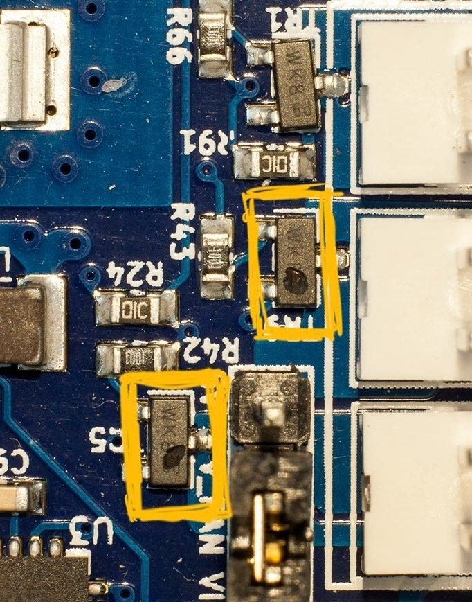
Otherwise, check the fan mosfets beside the fan ports for any visible damage.
https://duet3d.dozuki.com/Wiki/Connector_and_spare_part_numbers#Section_Fan_mosfet
-
Thanks... you are right... both mosfests lifted there housing for better ventilation.
Shit... No, I will not replace it, This is the size of components which I will not touch with a soldering iron any more. ") I will talk with my hardware developer, he may trust himself enough to replace them.
I will talk with my hardware developer, he may trust himself enough to replace them.Fan 2 seems still OK, so I will use that one till I blow him off, too
But here comes the next question. I measure something around 12V to 13V on the FAN 3 when I turn it on to 100%. I expect 24V (VIN) there.I have the 12V fans connected to the Duex and the 24V connected to the Duet. Can this have any impact?
Cheers, Chris
Edit:
M563 P0 S"Extruder" D0 H1 F0Do not make any difference.
-
ouch, optical aids may help of hands are still steady. they're really not that small when considering the space between the pads. on the other hand there is very little room between the mosfet and the fan header - removing the plastic header temporarily makes it easier.
spare parts: https://duet3d.dozuki.com/Wiki/Connector_and_spare_part_numbers#Section_Fan_mosfet
and complete schematics if needed: https://github.com/T3P3/Duet/tree/master/Duet2
-
@bearer
Sure... My current math is easy here: I have one 24V fan connected on that board and I have one last mosfet left. So no need to put any pressure her, as long as I do not mess up the last remaining.
And I want to continue my corexy build, the CR10 should print the parts for it at the moment only.
Cheers, Chriss
-
@Chriss said in Fan stoped working:
So no need to put any pressure her, as long as I do not mess up the last remaining.
if it ain't broke .. you're not trying hard enough!
- AvE -
@bearer
Sooooo true...I hope that somebody will jump in and help me to understand the voltage problem. I'm very confused about all of that. The fan was working very fine till yesterday. I printed a holder for the ir-probe for the new corexy and realized that the fan is not working any more. And I have two problems now? Very unlikely.....
Cheers, Chriss
-
@Chriss said in Fan stoped working:
I hope that somebody will jump in and help me to understand the voltage problem.
you should probably elaborate a little on where the measurement is done. if between the two pins on the fan output then a failed mosfet can explain it.
if you're measuring Vfan with respect to ground on say Vin then the only thing between Vin an Vfan is a fuse and a jumper - measure the resistance in that path.
-
@bearer
I hoped that I was clear enough but sure, I can elaborate it more:
I connected the fan to "FAN2" now, (because FAN[0|1])are gone. I used only some jumper wires and have the multi meter connected parallel to the fan.
Regular setup = 12-13V
Between FAN2- and VIN = 12-13V
Between FAN2+ and GND = 24VI jumperd the Duex to supply 12V for the fans. My former experience was that the the Duet provided 24V because the fan was spinning. But I see 12V now. Does that makes sense to you?
-
Not unless Fan2 has also failed, just less spectacularly.
There aren't any other connections between the Duet and the Duex than the ribbon cable, 24v and ground? Having Vfan in the Duex set to 12v shouldn't affect the Duet2 Vfan unless there is a short in wiring somewhere afaik. (though that might explain the failure in the first place)
-
@bearer said in Fan stoped working:
Not unless Fan2 has also failed, just less spectacularly.
That should not be the case, I measure 12V there.
There aren't any other connections between the Duet and the Duex than the ribbon cable, 24v and ground?
Nope, no connection
Having Vfan in the Duex set to 12v shouldn't affect the Duet2 Vfan unless there is a short in wiring somewhere afaik. (though that might explain the failure in the first place)
And it worked till yesterday....
I may have blown up the mosfet while I tried to debug the "not so spinning fan". But that was the only change I know about. -
@Chriss said in Fan stoped working:
That should not be the case, I measure 12V there.
they don't always fail as a a short or open circuit. if you measure the gate signal to be doing the correct thing but not the drain then its probaly done for.
-
@bearer
But the mosfed is still adjustable, the voltage drops down to 11-12V when I reduce the fan to 86%. I have never seen a mosfet working like that when it is broken, did you?
-
can't say i have but as the source goes straight to ground and you're dropping 12v between drain and ground then the options are limited?
-
@bearer
It is official now: I'm totally confused now.
I have 20V on gate. 20? How? I would have expected 24V here, am I right?
(Yes, it is accurate, only the 3rd digit after the "dot" is going up and down one micro volt. Yes, I trust my Keithley multi meter.) -
@Chriss said in Fan stoped working:
I have 20V on gate. 20? How? I would have expected 24V here, am I right?
check your wiring - the gate is driven from the ATSAM directly (through a small resistance), so 3.3v max

ref https://github.com/T3P3/Duet/raw/master/Duet2/Duet2v1.04/Duet2_1.04c_Schematic.pdf
-
@bearer
You where right... I know now where the 20V came from. Let us forget that post, please.You are right, there are 3,3V on the gate when I have the fan at max and close to 0 when the fan is at 0%. Let me guess: The mostfet has passed away too?
-
either the mosfet is dropping 12v drain to source, or the board is dropping 12v from source to ground - either way something needs fixing as far as I can tell.
less than 1v drain to ground when on and loaded is okay
i suppose you could power down and see if you can measure any resistance from drain to source, or source to ground.
-
@bearer
Source to ground: 93Ohm, this are my wires.
Drain to source: 24,7kOhm -
@bearer @Phaedrux
Just as an idea: Can I use the "ground" from a fan on the expansion (configured to provide 12V) board and VIN (24V) to control the 24 fan?
I need to get that fan back working and it seems to me like all three pwm's on the mainboard ore dead.
Cheers, Chriss