Homeing does not work - fadeing x Endstop
-
Sended M115; Response: FIRMWARE_NAME: RepRapFirmware for Duet 2 WiFi/Ethernet FIRMWARE_VERSION: 2.03 ELECTRONICS: Duet Ethernet 1.02 or later FIRMWARE_DATE: 2019-06-13b2
Config File:
; Configuration file for Duet WiFi (firmware version 2.03)
; executed by the firmware on start-up
;
; generated by RepRapFirmware Configuration Tool v3.1.4 on Sat Jul 18 2020 12:48:35 GMT+0200 (Mitteleuropäische Sommerzeit)

; General preferences
G90                                                ; send absolute coordinates...
M83                                                ; ...but relative extruder moves
M550 P""                             ; set printer name
M918 P1 E4 F2000000                                ; configure direct-connect display

; Network
M551 P""                               ; set password
M552 P0.0.0.0 S1                                   ; enable network and acquire dynamic address via DHCP
M586 P0 S1                                         ; enable HTTP
M586 P1 S0                                         ; disable FTP
M586 P2 S0                                         ; disable Telnet

; Drives
M569 P0 S0                                         ; physical drive 0 goes backwards
M569 P1 S0                                         ; physical drive 1 goes backwards
M569 P2 S0                                         ; physical drive 2 goes forwards
M569 P3 S0                                         ; physical drive 3 goes backwards
M584 X0 Y1 Z2 E3                                   ; set drive mapping
M350 X16 Y16 Z16 E16 I1                            ; configure microstepping with interpolation
M92 X80.00 Y80.00 Z400.00 E93.00                   ; set steps per mm
M566 X1200.00 Y1200.00 Z24.00 E300.00              ; set maximum instantaneous speed changes (mm/min)
M203 X9000.00 Y9000.00 Z180.00 E6000.00            ; set maximum speeds (mm/min)
M201 X500.00 Y500.00 Z100.00 E5000.00              ; set accelerations (mm/s^2)
M906 X800 Y800 Z800 E1000 I50                      ; set motor currents (mA) and motor idle factor in per cent
M84 S30                                            ; Set idle timeout

; Axis Limits
M208 X0 Y0 Z0 S1                                   ; set axis minima
M208 X235 Y235 Z260 S0                             ; set axis maxima

; Endstops
M574 X1 Y1 Z1 S1                                   ; set active high endstops

; Z-Probe
M307 H4 A-1 C-1 D-1                                ; disable heater on PWM channel for BLTouch
M558 P9 H5 F120 T6000                              ; set Z probe type to bltouch and the dive height + speeds
G31 P500 X0 Y0 Z2.5                                ; set Z probe trigger value, offset and trigger height
M557 X15:215 Y15:195 S20                           ; define mesh grid

; Heaters
M305 P0 T100000 B4092 R4700                        ; set thermistor + ADC parameters for heater 0
M143 H0 S150                                       ; set temperature limit for heater 0 to 150C
M305 P1 T100000 B4092 R4700                        ; set thermistor + ADC parameters for heater 1
M143 H1 S275                                       ; set temperature limit for heater 1 to 275C

; Fans
M106 P0 S0 I0 F500 H-1                             ; set fan 0 value, PWM signal inversion and frequency. Thermostatic control is turned off
M106 P1 S1 I0 F500 H1 T45                          ; set fan 1 value, PWM signal inversion and frequency. Thermostatic control is turned on
M106 P2 S1 I0 F500 H1:0 T45                        ; set fan 2 value, PWM signal inversion and frequency. Thermostatic control is turned on

; Tools
M563 P0 D0 H1 F0                                   ; define tool 0
G10 P0 X0 Y0 Z0                                    ; set tool 0 axis offsets
G10 P0 R0 S0                                       ; set initial tool 0 active and standby temperatures to 0C

; Custom settings are not defined

; Miscellaneous
M911 S10 R11 P"M913 X0 Y0 G91 M83 G1 Z3 E-5 F1000" ; set voltage thresholds and actions to run on power loss
I have a name and password, but I deleted it only in this post
")
-if you see anything where i should add / change something... feel free to tell me - I am a reprap noob
Joe
-
@humbleJoe said in Homeing does not work - fadeing x Endstop:
M918 P1 E4 F2000000
Direct connect display (eg 12864) is not supported on Duet 2 Wifi, only Maestro. Well, it sort-of is, but you need an adapter board and a special version of the firmware. If you've connected a screen, disconnect it.
FIRMWARE_VERSION: 2.03
That is an old version of the firmware, ideally update to the latest v2 firmware, which is 2.05.1. But your config.g should work with it.
Generally, I can't see much wrong with your config.g. Please check your X endstop is wired correctly, as I think it's most likely that's what's causing the problem. See https://duet3d.dozuki.com/Wiki/Connecting_endstop_switches#Section_Connecting_different_types_of_endstop_switch
You could try swapping the X and Y endstop connection, and see if the behaviour swaps to the Y axis.
Finally, at the moment your homing files are not set up to use the BLTouch for homing Z; they're using a Z endstop. Replace these lines in homeall.g and homez.g:
G1 H1 Z-265 F240        ; move Z down stopping at the endstop
G90                     ; absolute positioning
G92 Z0                  ; set Z position to axis minimum (you may want to adjust this)
with
G90                     ; absolute positioning
G1 X15 Y15 F6000        ; go to first bed probe point and home Z
G30                     ; home Z by probing the bed
Ian
-
So my homez.g now looks like:
; homez.g
; called to home the Z axis
;
; generated by RepRapFirmware Configuration Tool v3.1.4 on Sat Jul 18 2020 12:48:36 GMT+0200 (Mitteleuropäische Sommerzeit)
G91               ; relative positioning
G1 H2 Z5 F6000    ; lift Z relative to current position

G90                     ; absolute positioning
G1 X15 Y15 F6000        ; go to first bed probe point and home Z
G30                     ; home Z by probing the bed

; Uncomment the following lines to lift Z after probing
;G91              ; relative positioning
;G1 Z5 F100       ; lift Z relative to current position
;G90              ; absolute positioning
and the homeall.g is
; homeall.g
; called to home all axes
;
; generated by RepRapFirmware Configuration Tool v3.1.4 on Sat Jul 18 2020 12:48:36 GMT+0200 (Mitteleuropäische Sommerzeit)
G91                     ; relative positioning
G1 H2 Z5 F6000          ; lift Z relative to current position
G1 H1 X-240 Y-240 F3000 ; move quickly to X and Y axis endstops and stop there (first pass)
G1 H2 X5 Y5 F6000       ; go back a few mm
G1 H1 X-240 Y-240 F240  ; move slowly to X and Y axis endstops once more (second pass)
G90                     ; absolute positioning
G1 X15 Y15 F6000        ; go to first bed probe point and home Z
G30                     ; home Z by probing the bed

; Uncomment the following lines to lift Z after probing
;G91                    ; relative positioning
;G1 Z5 F100             ; lift Z relative to current position
;G90                    ; absolute positioning
Is that correct
?And the endstop is wired like this: on the duet mainboard only the two outer pins, (GND,
3v3,X Stop). on the ender 3 side i have the following pinout: (Signal, Ground,3v3). So I wired GND -> GND, X Stop -> Signal and both 3v3 are not used.Thx for the help.
Joe -
So I now changed the X Endstop with the Z Endswitch because I dont use it anymore. It still doesnt work.
After changing the lines shown in the last 2 posts I tryed to only home Z.
The Z axis only moved some milimeters positive direction and then stopped and the webpage gave me this error.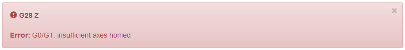
If I press home all the x axis moves some mm, the y as well (both x and y home buttons then switch to homed) and then the Z axis starts moveing down and never stops, the BL Touch also dont work correct, it was always closed / triggered - like it behaves while printing.
So i had to emergency stop just before the print had reached the bed - cause it would not have stopped.
This error came after restart
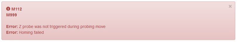 .
.FYI: When I power on the printer the BL Touch does this start process where it tests that it can trigger correct and that works every time.
-> can someone tell me what the F is wrong with my setup? Before I switched from the Creality Mainboard v. 1.1.5 everything worked fine so I would guess all this behaviour must be from mistakes in wireing or firmware.
however I feel like the wiring is as it is shown in the wiki. -
@humbleJoe said in Homeing does not work - fadeing x Endstop:
M307 H4 A-1 C-1 D-1
Where do you have the BLtouch wired up to? H4 is certainly incorrect. It should either be heater pin 3 or 7. Without that being correct you can't deploy or retract the pin.
-
@Phaedrux said in Homeing does not work - fadeing x Endstop:
@humbleJoe said in Homeing does not work - fadeing x Endstop:
M307 H4 A-1 C-1 D-1
Where do you have the BLtouch wired up to? H4 is certainly incorrect. It should either be heater pin 3 or 7. Without that being correct you can't deploy or retract the pin.
You are correct, it is H3/ Pin 8. I connected the BL Touch the recommended way from the wiki:
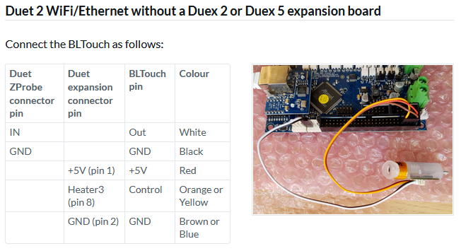
Thx for this hint - this was an user error ^^.
I will fix this after work and also review the rest of my code configurations before I waste your time
-
so here is an Update:
after getting the BL Touch right and fixing the following files:config.g
; Configuration file for Duet WiFi (firmware version 2.03)
; executed by the firmware on start-up
;
; generated by RepRapFirmware Configuration Tool v3.1.4 on Sat Jul 18 2020 12:48:35 GMT+0200 (Mitteleuropäische Sommerzeit)

; General preferences
G90                                                ; send absolute coordinates...
M83                                                ; ...but relative extruder moves
M550 P""                             ; set printer name
M918 P1 E4 F2000000                                ; configure direct-connect display

; Network
M551 P""                               ; set password
M552 P0.0.0.0 S1                                   ; enable network and acquire dynamic address via DHCP
M586 P0 S1                                         ; enable HTTP
M586 P1 S0                                         ; disable FTP
M586 P2 S0                                         ; disable Telnet

; Drives
M569 P0 S0                                         ; physical drive 0 goes backwards
M569 P1 S0                                         ; physical drive 1 goes backwards
M569 P2 S0                                         ; physical drive 2 goes forwards
M569 P3 S0                                         ; physical drive 3 goes backwards
M584 X0 Y1 Z2 E3                                   ; set drive mapping
M350 X16 Y16 Z16 E16 I1                            ; configure microstepping with interpolation
M92 X80.00 Y80.00 Z400.00 E93.00                   ; set steps per mm
M566 X1200.00 Y1200.00 Z24.00 E300.00              ; set maximum instantaneous speed changes (mm/min)
M203 X9000.00 Y9000.00 Z180.00 E6000.00            ; set maximum speeds (mm/min)
M201 X500.00 Y500.00 Z100.00 E5000.00              ; set accelerations (mm/s^2)
M906 X800 Y800 Z800 E1000 I50                      ; set motor currents (mA) and motor idle factor in per cent
M84 S30                                            ; Set idle timeout

; Axis Limits
M208 X0 Y0 Z0 S1                                   ; set axis minima
M208 X235 Y235 Z260 S0                             ; set axis maxima

; Endstops
M574 X1 Y1 Z1 S1                                   ; set active high endstops

; Z-Probe
M307 H3 A-1 C-1 D-1
M558 P9 H5 F100 T2000
G31 X0 Y0 Z0 P25
M557 X15:215 Y15:195 S20                           ; define mesh grid

; Heaters
M305 P0 T100000 B4092 R4700                        ; set thermistor + ADC parameters for heater 0
M143 H0 S150                                       ; set temperature limit for heater 0 to 150C
M305 P1 T100000 B4092 R4700                        ; set thermistor + ADC parameters for heater 1
M143 H1 S275                                       ; set temperature limit for heater 1 to 275C

; Fans
M106 P0 S0 I0 F500 H-1                             ; set fan 0 value, PWM signal inversion and frequency. Thermostatic control is turned off
M106 P1 S1 I0 F500 H1 T45                          ; set fan 1 value, PWM signal inversion and frequency. Thermostatic control is turned on
M106 P2 S1 I0 F500 H1:0 T45                        ; set fan 2 value, PWM signal inversion and frequency. Thermostatic control is turned on

; Tools
M563 P0 D0 H1 F0                                   ; define tool 0
G10 P0 X0 Y0 Z0                                    ; set tool 0 axis offsets
G10 P0 R0 S0                                       ; set initial tool 0 active and standby temperatures to 0C

; Custom settings are not defined

; Miscellaneous
M911 S10 R11 P"M913 X0 Y0 G91 M83 G1 Z3 E-5 F1000" ; set voltage thresholds and actions to run on power loss
deployprobe.g
M280 P3 S10 I1retractprobe.g
M280 P3 S90 I1Here is what happens:
When I home X and Y axis, the printhead moves z positive, some mm (less then 5) into x/y positive direction (my endstops are low end/ so other direction and will never get triggered) and then z negative and stops there.-> he thinks the home was a success!
The Z homeing works now (or at least it tests it once, the second / faster test doesnt work).After homeing all axis (doesnt matter if allhome/ or to home 1 by 1) the printer thinks that the point he is at the moment is his home (even if it is in the middle of the build plate because he never drives to the endstops). So i can move the X and Y axis only in more positive direction but not nevative (as long as I dont move positive first. then I am able to drive as much negative as I did positive before.)
Edit:
One other thing about the endstops. at the moment I used normaly open switches because i was not able to use normaly closed once - changeing the 1 to 0 and 0 to 1 in the config.g made no diffrenceEndstops M574 X1 Y1 Z1 S1same behavior as
Endstops
M574 X0 Y1 Z1 S1
How can this be?
Any tipps what I can do next -
Hi,
So when you home X or Y the result is some small movement on X or Y in the positive direction.
Correct?
If so that is because your end stops are already triggered when the home begins.
- The 1st move in the negative direction never happens because the end stop is triggered
- The 2nd move in the positive direction happens as expected giving the 5 mm of movement in the positive direction
- The 3rd move in the negative direction never happens because the end stop is triggered
Try changing the M574 command to specify active low if it is now active high (or vice versa).
Frederick
-
Hi,
well thx for this hint. I directly homed again while holding the x endstop and it works as it should until I let it again.
So now my question is why is it that my machine thinks he is always triggered even when the Endstop LEDs are not shineing. -> why doesnt it work when i change the M574 command from X0 to X1 or other direction or die S1 to S0?Greetings
JoeEdit:
I use NO Switches with 2 wires. So I wired only the 2 outer pins as said in this wiki: https://duet3d.dozuki.com/Guide/2.)+Wiring+your+Duet+2+WiFi-Ethernet/9?lang=en
And I have the config.g as posted above. what would be the correct commands for my ender 3 with this setup? can anybody tell me I will test it then -
Hi,
In the M574 the number after the X,Y,Z specifies if the end stop is at the low or high end of the axis range.
S1 specifies an active high input, S0 specifies active low.
You need to use S0 since your switches, when closed, connect the input to ground.
Frederick
-
Ok, then I have understood that correctly. So here is my endstop config from config.g
Endstops
M574 X1 Y1 Z1 S0
and this is how i wired the x and y endstops on the duet:

this is how both endstops (normaly closed) are connected:

but they behave weird. When I interrupt the connection (pushing the trigger or just disconnect the switch) the red LED goes off and i am able to home correct. -> so the FW works as NO Switches.
Here I have the x-endstop just connected and the board thinks it is triggered when it is not, but the disconnected y is not "triggered".
In my understanding it shouldnt behave like this - might there be an overwrite file where I also have to change something because inverting the config.g to S0 or S1 makes both no diffrence in behaviour.
But when I change thw wires on the switch side to NO it works fine. How ever I want to use them in NC mode.
BTW can i scale the images down in this view ? that i dont spam pages ?
Joe
-
Where are your endstops actually located? Left/right front/back?
Low end of travel is to the left, high end to the right.
Low end to the front, high end to the back.
-x to the left, +x to the right.
-y to the front, +y to the back.Your homeall file is setup for the switches to be at the low ends of travel. Is that still the case?
What does your M574 line look like now?
For the Ender 3 pro in RRF2 it should be
M574 X1 Y1 Z1 S1 -
Hi,
I havent changed anything on the positioning of the ender 3 pro switches. So when I look at my printer the x is on left side and the y on the back.
In the config.g file the M574 command is
; Endstops
M574 X1 Y1 Z1 S1
Ok for reasons that I dont understand the homeing process now works as intended. exept for one little detail. it trys to home the z axis with the BL Touch on spot near the x endstop so out of the heated bed. How do I fix this :)?
The x & y endstop LED is always on when not triggered. I asume that is fine?!
When Y triggered the LED goes off how ever when X is triggered the LED goes from bright shine to low dimmed but not off. -> is that a problem / do you guys have that behavior as well?Joe
-
@humbleJoe said in Homeing does not work - fadeing x Endstop:
of the heated bed. How do I fix this :)?
Edit x and y position in homeall.g and homez.g
G1 X15 Y15 F6000 ; go to first bed probe point and home Z -
@humbleJoe said in Homeing does not work - fadeing x Endstop:
Ok for reasons that I dont understand the homeing process now works as intended. exept for one little detail. it trys to home the z axis with the BL Touch on spot near the x endstop so out of the heated bed. How do I fix this :)?
For this purpose I would do it at the center of the bed.
Now I prefer setting up axis min/max values so 0,0 IS the center of the bed.
So for my FT-5 with a 300x300 bed the X and Y axis min/max values are -150/150.
IF I kept 0,0 at the left-front corner the X and Y axis min/max values would be 0/300.
In that case to probe at the center I would have to use 150,150.
Someone else has suggested using the first probe point at 15,15 - not sure why you would want to do that.
Frederick
-
Looks good now, changed x & y to 118 (235/2).
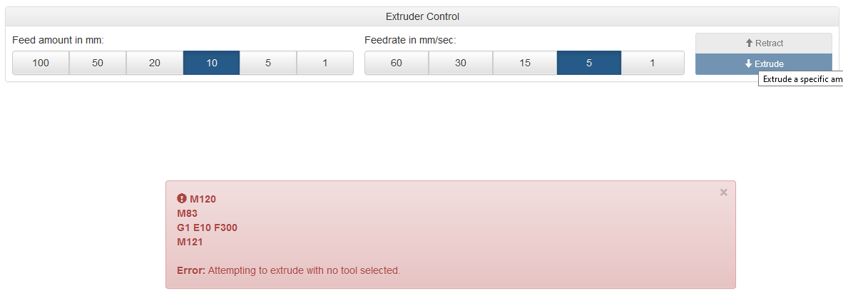
So thank you all for helping meHowever one last point. It looks like my Extruder is not set up correctly.
I cant extrude or retract something an when clicking on it I get the following error.
Joe
-
Select a tool first by either clicking on the tool, or sending T0. Most people add a T0 to the end of config.g so that it's selected at start up. It also must be at temp to extrude unless you've specifically allowed cold extrusion.
-
Thank you all so much. Works everything fine now.... I will read some more wiki and learn all this machine code
but thank you all for the support Greetings and have good prints!
Joe