Battling sources of vibration and noise
-
@Nxt-1 Oh no, I wouldn't wish that on anyone - changing boards, and all that goes with it, is a pita. More of a thought, but I can 100% state that when I had a skr1.4pro+2209s on my printer it was dead quiet, now that controller is in my kids printer - which is cool because I don't hear it. I'd say maybe the duet2 is just a bit louder for me, but not much, but I like RRF much better then others and I trust the board fully.
Having an office discussion about this (note: we're not in the 3d printer business), we pretty much all agree that the steps we would take would be to completely isolate the upper and lower portion of the drive train - or at least as much as feasible. Then, from there, it would easier at each step to lessen the residual effects.
Keep a follow up, hope you obtain a solution

-
@Nxt-1, also was wondering what your config has for this motor, how many amps are you putting to it and have you tried to reduce this a bit to see if that lessens the noise while keeping physical performance in check?
-
This must rate a solid 8.63/10 on the universal jankiness scale but it is a proof of concept right. While not 100% effective, the noise levels are cut down to quite acceptable I'd say. Note, on the pulley axle under the rubber strips, bearings sit on the axle. So the 'belts' are not rotating.
For something more permanent I am thinking of mounting the bearing in a thick rubber piece (like a 10mm thick washer but then made from rubber). And then mounting the rubber into something more rigid. I'm also wondering weather the TPU I have laying around could serve for the rubber purpose. Datasheet hardness is 95 Shore A. I am not sure if I should look into stiffer or just the opposite.

@Kolbi said in Battling sources of vibration and noise:
@Nxt-1, also was wondering what your config has for this motor, how many amps are you putting to it and have you tried to reduce this a bit to see if that lessens the noise while keeping physical performance in check?
The motors I use are Oriental Motors PKP266MD28B (2.8A rated) and I am running them at the full 2,4A the duet has to offer. Reducing the current does reduce the vibration, yet I'd like to keep that option as an ultimate last resort.
-
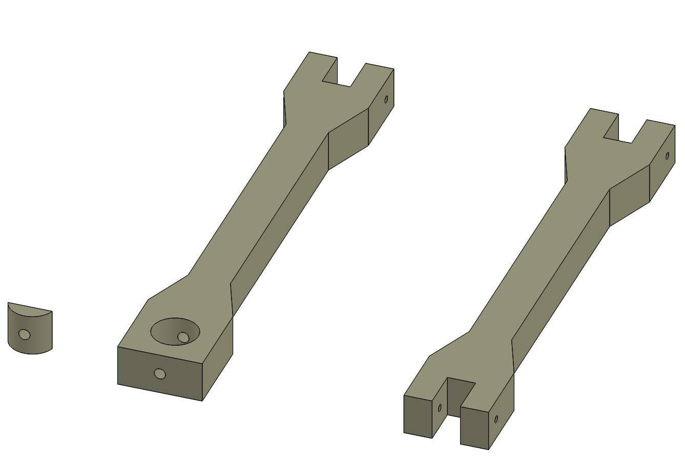
@Nxt-1 funny enough - I was thinking of a semi-rigid dog-bone linkage as well. The dog on the left would be for running a bolt up through the center with the nut on top of the insert, whereas the one on the right would be using a bolt's eye or similar.
Depending on available tools and materials, it may be much easier and faster to design hard ends (printed) with rubber attached between? I do remember making custom polyurethane bushings for a car project - maybe you could design a mold and do similar, that would be spot on.
-
@Kolbi said in Battling sources of vibration and noise:
@Nxt-1 funny enough - I was thinking of a semi-rigid dog-bone linkage as well. The dog on the left would be for running a bolt up through the center with the nut on top of the insert, whereas the one on the right would be using a bolt's eye or similar.
Depending on available tools and materials, it may be much easier and faster to design hard ends (printed) with rubber attached between? I do remember making custom polyurethane bushings - maybe you could design a mold and do similar, that would be spot on.I fail to understand how your linkages work or are installed. I am not saying they don't work, I just not following what they do and how they fit in the machine in what orientation

To be honest they way I did it in the picture was just to verify that isolating the bearing would do the trick in terms of noise reduction. I was originally thinking of designing a bracket very similar to the printed one I was using previously, just with more room to accommodate a rubber bushing.
I literally just found a possible source for a rubber bushing in the size I need (12mm ID) but generally I have trouble sourcing these. So I started looking more into DIY solutions got some type B cylindrical vibration dampers from a local hardware store and drilled the threaded hole out to 12mm. What do you know, there is no metal left in the pocket, doh. (and M12 size dampers are way to large) See the right most thing on the picture
Next I got some type D cylindrical vibration dampers and with much struggle managed to make a 'hole' in the flat end where a bearing can fit in. I am not convinced this is the way to go as machining rubber is an absolute nightmare without stuff like dry ice to harden the rubber. That being said, doing it this way leaves me with two mounting options, one bushing style and one with the threads on either side. I'll continue to work on this and keep updating as I go


-
@Nxt-1 said in Battling sources of vibration and noise:
how your linkages work or are installed
Two different designs, one of left is for bolt / threaded rod attachment, one on right is for bolt that would have an 'eye' on it.
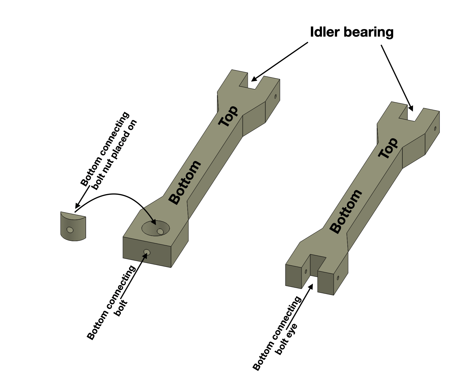
On casting polyurethane: https://youtu.be/gFJqBJleiVY
-
@Kolbi That explains it, I understand now.
I have no experience with polyurethane but most seem to dangle around 80 shore D, which seems way to stiff for use in a bushing like this. I expect it to inadequately isolate the vibrations. However casting a bushing myself might be a good idea, albeit from a softer material I'd say, something like a stiff silicone maybe 70 shore A or something.
-
@Nxt-1, from what I remember you can vary the mix to obtain the hardness desired. Guess it really depends on what type of kits are available in your area/shipping restrictions and such, and how it is designed. So if it is a stiffer material you could then 'thin' the connecting structure to allow absorption of the offending frequencies.
I have seen some formulas to help determine such but I think in the end, it really comes down to trial, error, error-correction, and then winning - but that's what makes the process fun and rewarding. Also remember that whatever material you choose to go with, it will be subjected to a heated environment and its properties may change - so do testing at room temp and again at the expected chamber temp. -
@Nxt-1 one option (though may be hard to implement) would be to use standard nitrile/nbr o-rings. They're usually about 70 shore A and you can get them in a range of sizes. Maybe have two on the OD of the bearing and a smaller one for it to butt up against axial?
-
@engikeneer That's a creative idea, I'll keep that in mind.
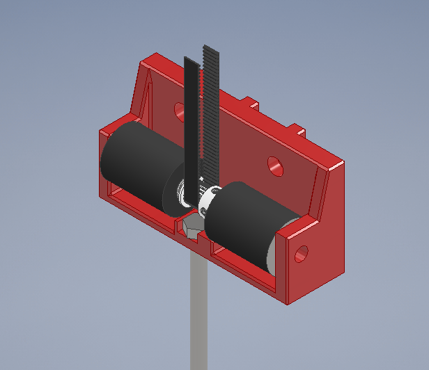
For now I just finished designing a revised bracket similar to what I had originally. It has gotten quite a bit wider to accommodate the two dampers but there is width-space available. Since doing the enclosure stuff I actually don't have a working printer at the moment so I'll get that sorted out first and we'll see from there.
-
The shear loading on the rubber you have in that bracket seems less than optimal.
Personally I'd be trying for something in-line similar to @Kolbi 's suggestion.
And @engikeneer 's suggestion of o-rings seems like both the easiest and best...I'd use a larger OD bearing (any specific reason you used needle bearings?), and use some nice fat silicone o-rings. That way you are not putting shear load on the soft material.
Easy to modify your new bracket to get that too.
-
@theruttmeister said in Battling sources of vibration and noise:
The shear loading on the rubber you have in that bracket seems less than optimal.
At the time you made your post, I was already printing the first bracket in this style. So I tried it out and you are definitely right, shear loads are not idea and in this case the loads were to large, causing unacceptable deflection.
Personally I'd be trying for something in-line similar to @Kolbi 's suggestion.
There are a couple difficulties I see with the soft dog-bone style. One, if you make to linkages, they need to be absolute same length, even under load. Otherwise the axle sits at an angle, in turn causing belt tracking problems. Two, I don't really have a good way of making rubber-ish shapes like that (except for printing them in tpu maybe), nor do I have a good source for rubber material that thick. Finally, and maybe most important of the three. If I understand the design correctly, you have a rigid bracket locating the bearings and that bracket is decoupled using the rubber-ish dog-bone links. This still allows for the bracket to vibrate and I believe that the bracket itself is emitting noise, not just coupling it further down the frame.
And @engikeneer 's suggestion of o-rings seems like both the easiest and best...
I agree, yet I had trouble sourcing o-rings (round or ideally square) in the size I need, especially the thickness proves to be and issue. And I am not a fan of doubling or even tripling up on thinner o-rings, because keeping them in place reliable becomes more difficult I think.
In the end I did more or less go the o-ring approach though
 I got myself some more of the type e dampers and cut them into pucks the thickness I need. Then I constructed a diy cork borer by sharpening a piece of metal tubing and printing an adapter so I could chuck in my drill. I used that device to drill the center holes, where the bearings sit and it worked surprisingly well.
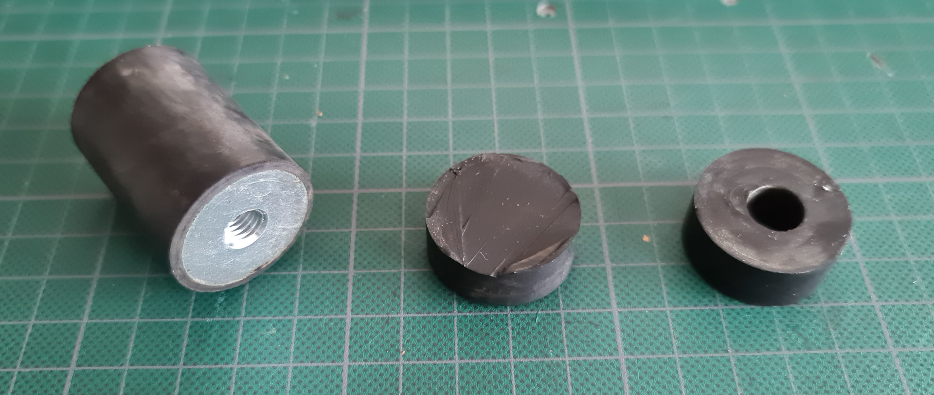
After some more bracket redesigning I ended up with this. It's fairly compact, easy to install and tension and does what it is supposed to do.
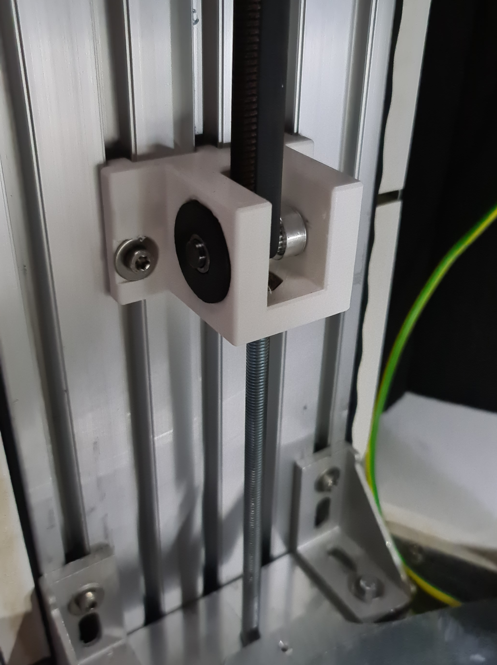
This upgrade brought the noise levels down low enough that you can still hear the machine running on some moves from the next room if it is really quiet. So not perfect but we are definitely getting closer and closer. The next thing I have planned is to redesign the motor brackets to use this style of rubber washers as well. Even tough I have stated before that the upper bearing are not in play. I have some other changes I want to do to the brackets so why not squish the o-rings in there as well right.
-

I've seen a setup like this on a bio-chemistry machine. High precision, zero noise, a lot of speed. The difference is that it used woven nylon belts, ones like you would have as a seatbelt, instead of rubber. They stretch almost not at all but dampen the noise.
-
Your new bracket was exactly what I was imagining!
Although having access to McMaster, I would have probably used something like this:

@arhi
Interesting...
I imagine they allow the belt to vibrate, dissipating the energy, but not conduct it into something that makes unpleasant noises if it vibrates.
Clever use of two wildly different stiffness materials (the belts being much less stiff than 2 inch webbing). -
@arhi Always interesting to hear how they tackle similar issues in 'the big leagues'. I am not sure I see how nylon belts would dampen vibrations, but hey the ones who build machines like that are not the ones who starting threads on struggling with the issue

@theruttmeister Living in Belgium, McMaster is sadly not really an option for me

-
@Nxt-1 said in Battling sources of vibration and noise:
issues in 'the big leagues'
I saw many things in the "industry" / "big leagues" wrt belts that made very little sense to me. This "webbing" (that's the proper term for that seatbelt like strip?) is something I have seen a lot as pulley holders. OTOH a proper pillow blocks, fixed bearings and elastic link between motor and the rest of the machine is the main element "big leagues" use that we don't normally see on our printers. It both inprove precision big time and reduces noise. It increases compexity as you get to have 2 belts instead of one, or you get belt+leadscrew instead of just leadscrew, but the difference is significant
-
@arhi said in Battling sources of vibration and noise:
webbing
its what its refered to in more outdoorsy settings at least
-
@bearer said in Battling sources of vibration and noise:
@arhi said in Battling sources of vibration and noise:
webbing
its what its refered to in more outdoorsy settings at least
I watched adam savage make his new apron last night and he was referring to that strip as webbing so that + theruttmeister calling it webbing makes me assume that's the "common term"
 To be honest I don't even know the local term fot that strip
-
@arhi said in Battling sources of vibration and noise:
a proper pillow blocks, fixed bearings and elastic link between motor and the rest of the machine is the main element "big leagues" use that we don't normally see on our printers.
Can you elaborate, I interpret this as a motor with a pulley on its shaft. Connected with an elastic belt? to a second shaft that is supported by these pillow blocks. And from there a second belt (or just the shaft depending on the application) to output the power to wherever it's needed?
-
@Nxt-1 said in Battling sources of vibration and noise:
@arhi said in Battling sources of vibration and noise:
a proper pillow blocks, fixed bearings and elastic link between motor and the rest of the machine is the main element "big leagues" use that we don't normally see on our printers.
Can you elaborate, I interpret this as a motor with a pulley on its shaft. Connected with an elastic belt? to a second shaft that is supported by these pillow blocks. And from there a second belt (or just the shaft depending on the application) to output the power to wherever it's needed?
sorry that was not related to this webbing thing ..
the usual setup on these big expensive machines is
steel frame
on top of steel frame are 2 pillow blocks supporting the threaded rod
sometimes between pillow block and steel frame there is some "plastic" ~1-2mm thick plate (dunno what material it is but feels like plastic). One one side of the rod pillow block is "blind", on other side of the rod, rod protrudes from the pillow block, and have a pulley. Then next to it, parallel to the rod there is a motor with a pulley, two pulleys are linked with timed belt and motor is connected to the steel frame trough dampener (two steel plates connected with hard rubber allowing motor to "dance" and dampening any vibration between motor and frame) so motor-frame link is "soft", and motor-shaft link is "soft", no vibration transfered at all. Shaft-pillow is hard but pillow-frame is again "soft" link .. so the vibration transfer to the chasy is minimalwith the belt systems it's simpler but not much
on each side of the belt is a shaft with a pulley, shaft is supported by 2 bearings on each side of the shaft, one shaft is blind and that side usually have the "block" with 2 bearings and the shaft can slide on the chasy, again that block is connected to the chasy over a "plastic" plate (1-2mm thick). This is used to tighten the belt. If this side is unmovable then there is a third movable pulley that can tension the belt
The other side of the belt loop the shaft is one one side blind and on other side has pulley, again parallel to that shaft is a motor attached to chasy with dampener and a timed belt between motor and the shaft attached to the pulley engaging belt ..sorry for the txt explanation, I'm on vacation and not really visiting these facilities for almost a year due to covid so can't take any pictures but I think I clearly explained how it works.. basically motor is always linked to the "actuator" trough a belt and not directly, and the actuator is always stiff and hold it's own irrelevant to the drive train