oozeBot Elevate
-
edit 5/13/2021 - stealth edit as so much has changed, even the name. The name we'll launch with is the oozeBot Elevate. So any references below to the codename "ele^gant" can be ignored. Also, many of the features discussed have been changed over the course of R&D.
I decided to create a post where we can show our progress as we finalize the design and testing of our first commercially available printer - the oozeBot ele^gant (short for elevating gantry). For starters, here is the current custom boot logo for the PanelDue. We are also posting progress photos and videos on our instagram at instagram.com/oozebot
Feedback is welcome and appreciated, even critical!

-
Here is the current state of the electronics layout. Our machine is powered by a Duet 3 / RPi combo and the toolboard. Even though the photo only shows a single toolboard, we still utilized the tool distribution board as the next iteration will be add a second, independent, toolhead.
Note that our machine's z-axis utilizes belts. The first four relays on the relay board are used as z-brakes when power is cut. The other four relays are open for any other use.

-
Nice! feel free to post more photos here for those of us who don't want to login to instagram

-
Early look at our motion system travelling at 400mm/s:
It's too bad video can't be embedded.. or am I missing something?
-
@oozeBot If you can provide a link to the actual video file it embeds. I usually upload short videos to Imgur, which lets me easily grab a direct link.
-
I'm curious why you chose to go with a belt driven Z axis? Its certainly nice to watch.
And 400mm/s is nice, but your acceleration is fairly low. Acceleration generally makes a bigger difference to print times than top speed.
-
@theruttmeister said in oozeBot ele^gant:
I'm curious why you chose to go with a belt driven Z axis? Its certainly nice to watch.
And 400mm/s is nice, but your acceleration is fairly low. Acceleration generally makes a bigger difference to print times than top speed.
Oh, this was just a test I was doing on an early prototype to validate no steps were lost. You are right, acceleration was not set all that high.. but it sure was fun to watch it go round.

Early on, we had multiple iterations that used various combinations of lead screws (2, 3, and 4), but I wasn't satisfied. It wasn't until I realized I could use a bank of relays to create a z-brake that I became confident in the idea of switching the z-axis to use belts. I am extremely pleased with the final results. With the combination of the right steppers, belt tension, and the z-brake, absolutely no drop is experienced when power is cut! Plus it brought the overall cost down considerably..
-
@oozeBot Nice work, looks good!
I am wondering about z axis. What is the steps per mm / motor resolution? Are there any lifespan / maintenance considerations given the increased complexity for z, with regard to relays, brakes, ...
-
@Kolbi - first, all steppers we've chosen are LDO's new Class H (rated to 180° c) versions which can easily withstand our enclosure's target temp of 80° c.
For Z, we chose two LDO-42STH60-2004AH that have a 1.8° step angle coupled to GT2 16 tooth pulleys to increase resolution.
We will be very mindful to all lifespan / maintenance considerations, but at this time we do not have any concerns. We are using 9mm Gates fiber reinforced belts that are well within their intended use (example: same belts as used on the Shapeoko CNC). The relays only toggle on and off with power, so they should not prematurely wear out - plus we went with a board from Electronic-Salon that's using genuine Panasonic relays instead of some Chinese no-brands.
-
@oozeBot Thanks for the information. What sort of bed leveling will the machine use? At 100 steps/mm on Z would mesh present difficulties?
-
@Kolbi - we have not experienced any difficulties, but understand your thinking and we very well may change our minds yet again after more testing.
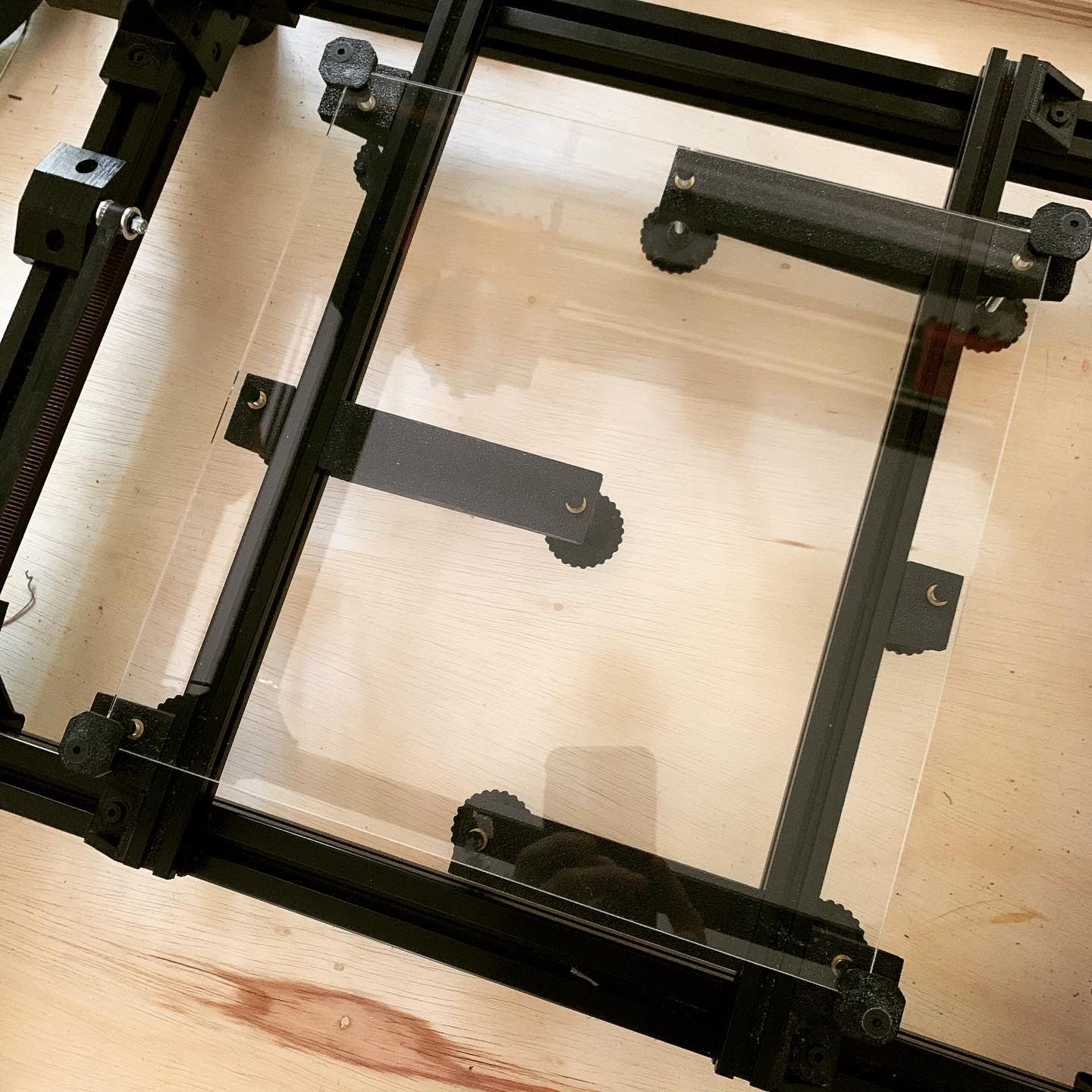
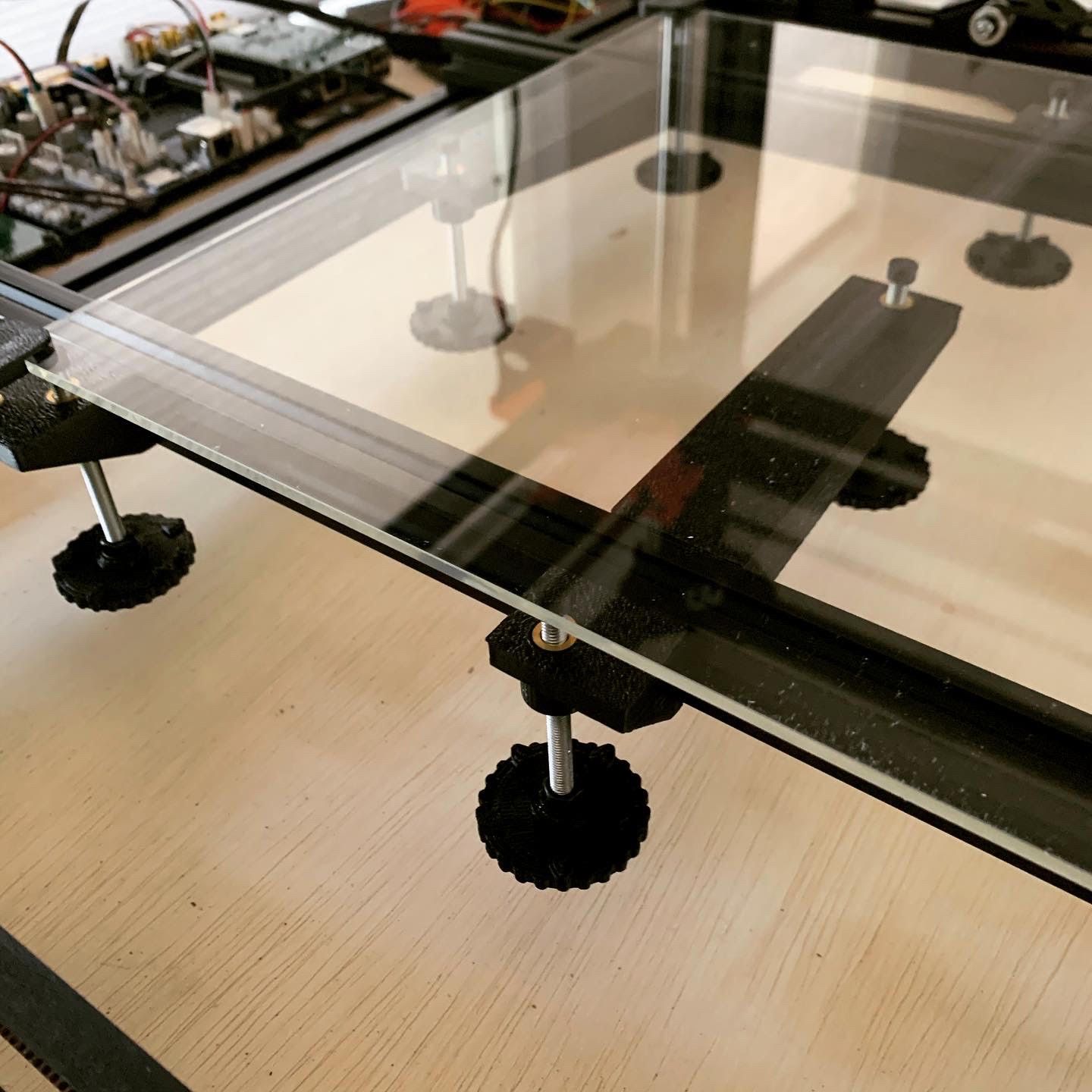
I guess I'm old school and firmly believe the best approach, by far, is manually leveling the bed prior to applying any mesh compensation. Our current 9 point manual leveling setup is shown below - the final design will utilize a 3rd extrusion instead of those long supports in the middle. FYI - our build plates will incorporate a Builtak flexplate system on top of the 3.3mm borosilicate glass, and a Keenovo heater underneath. The glass was laid down bare just to show it put together.
-
@oozeBot said in oozeBot ele^gant:
leveling the bed prior to applying any mesh compensation
I totally agree that the bed be leveled to the maximum extent possible, and if done well enough to forego mesh comp all together. Maybe I'd be slightly concerned with z-resolution + mesh comp, given a resolution of 10 microns. Not sure if it would be an actual issue or not.
-
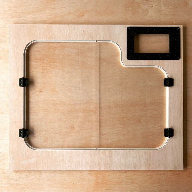
Sneak peek at the front of our prototype encloser.. fresh off the CNC! We’ll be using a 7” PanelDue as the screen.
-
Final version (hopefully) of our x-carriage and interchangeable tool heads! Any guesses on what the second tool is for? Just waiting on UPS to get that one finished up..

-
What machine printed those orange parts ?
-
@CaLviNx said in oozeBot ele^gant:
What machine printed those orange parts ?
At this point, everything has been printed on a previously designed machine that is not commercially viable. Hence why we are not talking about it. It's sort of the chicken vs egg argument as something had to create the first prototypes, right?
FYI - everything is printed in IC3D's ABS within a heated chamber. We tried several different materials and came back to ABS after finding the right balance of infill, perimeters, etc to give us the rigidity required to pass our QA.
-
@oozeBot said in oozeBot ele^gant:
@CaLviNx said in oozeBot ele^gant:
What machine printed those orange parts ?
At this point, everything has been printed on a previously designed machine that is not commercially viable. Hence why we are not talking about it. It's sort of the chicken vs egg argument as something had to create the first prototypes, right?
FYI - everything is printed in IC3D's ABS within a heated chamber. We tried several different materials and came back to ABS after finding the right balance of infill, perimeters, etc to give us the rigidity required to pass our QA.
What QA standard are you working to ?
-
@CaLviNx said in oozeBot ele^gant:
What QA standard are you working to ?
I do not want to mispeak on a public forum, so will have to defer and only state this type information is forthcoming.
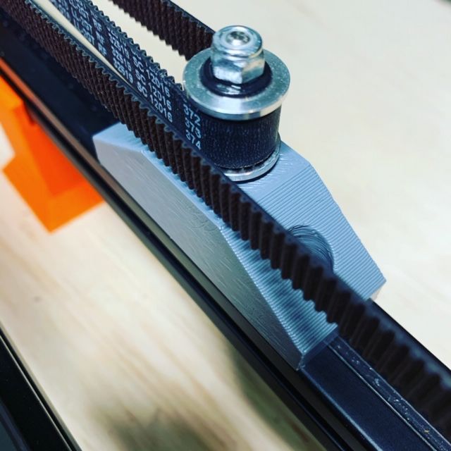
However, the specific QA test I was referring to when comparing materials were specific to heat (80c) and tension (>2x max belt tension).
Parts like this must be very rigid. The part shown was printed in polycarbonate. It worked well but turned out to be unnecessary as we achieved the same results with ABS.
-
For Quality Assurance I was referring to the international inspection standards.
For example the ISO standard or the ANSI standard.
The reason I asked is because I teach mechanical inspection engineering and we work to these international inspection standards.
I use these standards as a benchmark, we have a 3d printing department that I look after where we use 3d printing as a teaching tool, we encompass design, prototyping, material testing, material science etc, it allows me to get paid to play with my hobby.
-
@CaLviNx sounds like you just might be a good person to know as we move forward..! I'm sure we'll have questions.
