Duet3D Logo Duet3D
    • Tags
    • Documentation
    • Order
    • Register
    • Login

    help to setup M557 Mesh size

    Scheduled Pinned Locked Moved
    General Discussion
    6
    51
    2.0k
    Loading More Posts
    • Oldest to Newest
    • Newest to Oldest
    • Most Votes
    Reply
    • Reply as topic
    Log in to reply
    This topic has been deleted. Only users with topic management privileges can see it.
    • Vetiundefined
      Veti @lui2004
      last edited by

      @lui2004

      post a picture so that we can verify

      lui2004undefined 1 Reply Last reply Reply Quote 0
      • lui2004undefined
        lui2004 @Veti
        last edited by lui2004

        @Veti

        i have this mounted:
        https://www.thingiverse.com/thing:3781222

        and this is my acctual config:

        G31 P25 X41.2 Y4.5 Z1.051
        M557 X41.2:215 Y15:195 S20 ; define mesh grid

        1 Reply Last reply Reply Quote 0
        • jay_s_ukundefined
          jay_s_uk
          last edited by

          so assuming that 0 is on the left, the bltouch is mounted at X-41.2.

          where is Y when its homed?

          Owns various duet boards and is the main wiki maintainer for the Teamgloomy LPC/STM32 port of RRF. Assume I'm running whatever the latest beta/stable build is

          1 Reply Last reply Reply Quote 0
          • lui2004undefined
            lui2004
            last edited by

            Y is on 3

            1 Reply Last reply Reply Quote 0
            • jay_s_ukundefined
              jay_s_uk
              last edited by

              so...

              G31 P25 X-41.2 Y4.5 Z1.051
              M557 X41.5:215 Y15:195 S20                       ; define mesh grid
              

              Owns various duet boards and is the main wiki maintainer for the Teamgloomy LPC/STM32 port of RRF. Assume I'm running whatever the latest beta/stable build is

              1 Reply Last reply Reply Quote 0
              • lui2004undefined
                lui2004
                last edited by

                i have inserto your data now

                but now when i make G29 it will not measure all the left side

                see the video

                https://streamable.com/iga2jo
                
                1 Reply Last reply Reply Quote 0
                • PCRundefined
                  PCR
                  last edited by

                  try

                  G31 P25 X-41.2 Y4.5 Z1.051
                  
                  M557 X3:215 Y15:195 S20
                  
                  lui2004undefined 1 Reply Last reply Reply Quote 0
                  • lui2004undefined
                    lui2004 @PCR
                    last edited by

                    @PCR

                    hi

                    didnt work !

                    i will show you the video:

                    https://streamable.com/wpverc

                    1 Reply Last reply Reply Quote 0
                    • lui2004undefined
                      lui2004
                      last edited by

                      my config right now:

                      config.g:

                      ; Configuration file for Duet WiFi (firmware version 1.21)
                      ; executed by the firmware on start-up
                      ;
                      ; generated by RepRapFirmware Configuration Tool v2 on Tue May 07 2019 23:06:50 GMT+0100 (British Summer Time)
                      
                      ; General preferences
                      G90                                      ; Send absolute coordinates...
                      M83                                      ; ...but relative extruder moves
                      
                      ; Network
                      M550 P"Ender 5"                          ; Set machine name
                      M552 S1                                  ; Enable network
                      M586 P0 S1                               ; Enable HTTP
                      M586 P1 S0                               ; Disable FTP
                      M586 P2 S0                               ; Disable Telnet
                      
                      ; Drives
                      M569 P0 S1                               ; Physical drive 0 goes forwards
                      M569 P1 S1                               ; Physical drive 1 goes forwards
                      M569 P2 S0                               ; Physical drive 2 goes backwards
                      M569 P3 S0                               ; Physical drive 3 goes forwards
                      M584 X0 Y1 Z2 E3                               ; set drive mapping
                      M350 X16 Y16 Z16 E16 I1                 ; Configure microstepping with interpolation
                      M92 X80 Y80 Z800 E411.53        ; Set steps per mm
                      M566 X600.00 Y600.00 Z60.00 E300.00      ; Set maximum instantaneous speed changes (mm/min)
                      M203 X6000.00 Y6000.00 Z500.00 E6000.00  ; Set maximum speeds (mm/min)
                      M201 X500.00 Y500.00 Z100.00 E5000.00    ; Set accelerations (mm/s^2)
                      M906 X500.00 Y600.00 Z500.00 E600.00 I30  ; Set motor currents (mA) and motor idle factor in per cent
                      M84 S30                                  ; Set idle timeout
                      
                      ; Axis Limits
                      M208 X0 Y0 Z0 S1                         ; Set axis minima
                      M208 X220 Y220 Z300 S0                   ; Set axis maxima
                      
                      ; Endstops
                      M574 X1 S1 P"xstop"                            ; configure active-high endstop for low end on X via pin xstop
                      M574 Y1 S1 P"ystop"                            ; configure active-high endstop for low end on Y via pin ystop
                      ;M574 Z1 S1 P"zstop"                            ; configure active-high endstop for low end on Z via pin zstop
                      M574 Z0                                     ; configure Z-probe endstop for low end on Z
                      
                      M558 P9 C"^zprobe.in" H5 F120 T6000            ; set Z probe type to bltouch and the dive height + speeds
                      M950 S0 C"exp.heater7"                         ; create servo pin 0 for BLTouch
                      G31 P25 X-41.2 Y4.5 Z1.051
                      M557 X3:215 Y15:195 S20
                      
                      
                      ; Heaters
                      M308 S0 P"bedtemp" Y"thermistor" T100000 B4138 ; configure sensor 0 as thermistor on pin bedtemp
                      M950 H0 C"bedheat" T0                          ; create bed heater output on bedheat and map it to sensor 0
                      M307 H0 B0 S1.00                               ; disable bang-bang mode for the bed heater and set PWM limit
                      M140 H0                                        ; map heated bed to heater 0
                      M143 H0 S120                                   ; set temperature limit for heater 0 to 120C
                      M308 S1 P"e0temp" Y"thermistor" T100000 B3950  ; configure sensor 1 as thermistor on pin e0temp
                      M950 H1 C"e0heat" T1                           ; create nozzle heater output on e0heat and map it to sensor 1
                      M307 H1 B0 S1.00           
                      
                      ; Fans
                      M950 F0 C"fan0" Q500                           ; create fan 0 on pin fan0 and set its frequency
                      M106 P0 S0 H-1                                 ; set fan 0 value. Thermostatic control is turned off
                      M950 F1 C"fan1" Q500                           ; create fan 1 on pin fan1 and set its frequency
                      M106 P1 S1 H1 T45                              ; set fan 1 value. Thermostatic control is turned on
                      
                      ; Tools
                      M563 P0 D0 H1                            ; Define tool 0
                      G10 P0 X0 Y0 Z0                          ; Set tool 0 axis offsets
                      G10 P0 R0 S0                             ; Set initial tool 0 active and standby temperatures to 0C
                      
                      ; Automatic saving after power loss is not enabled
                      
                      ; Custom settings are not configured
                      M501
                      M575 P1 S1 B57600
                      

                      homeall.g

                      ; homeall.g
                      ; called to home all axes
                      ;
                      ; generated by RepRapFirmware Configuration Tool v3.1.4 on Tue Jul 28 2020 08:52:12 GMT+0200 (Mitteleuropäische Sommerzeit)
                      G91                     ; relative positioning
                      G1 H2 Z5 F6000          ; lift Z relative to current position
                      G1 H1 X-225 Y-225 F1800 ; move quickly to X and Y axis endstops and stop there (first pass)
                      G1 H2 X5 Y5 F6000       ; go back a few mm
                      G1 H1 X-225 Y-225 F360  ; move slowly to X and Y axis endstops once more (second pass)
                      G90                     ; absolute positioning
                      G1 X110 Y110 F6000       ; go to first bed probe point and home Z
                      G30                     ; home Z by probing the bed
                      
                      ; Uncomment the following lines to lift Z after probing
                      ;G91                    ; relative positioning
                      ;G1 Z5 F100             ; lift Z relative to current position
                      ;G90                    ; absolute positioning


                      homex.g

                      ; homex.g
                      ; called to home the X axis
                      ;
                      ; generated by RepRapFirmware Configuration Tool v2 on Tue May 07 2019 23:06:50 GMT+0100 (British Summer Time)
                      G91               ; relative positioning
                      G1 Z5 F6000 H2    ; lift Z relative to current position
                      G1 H1 X-225 F1800 ; move quickly to X axis endstop and stop there (first pass)
                      G1 X5 F6000       ; go back a few mm
                      G1 H1 X-225 F360  ; move slowly to X axis endstop once more (second pass)
                      G1 Z-5 F6000 H2   ; lower Z again
                      G90               ; absolute positioning
                      

                      homey.g

                      ; homey.g
                      ; called to home the Y axis
                      ;
                      ; generated by RepRapFirmware Configuration Tool v2 on Tue May 07 2019 23:06:50 GMT+0100 (British Summer Time)
                      G91               ; relative positioning
                      G1 Z5 F6000 H2    ; lift Z relative to current position
                      G1 H1 Y-225 F1800 ; move quickly to Y axis endstop and stop there (first pass)
                      G1 Y5 F6000       ; go back a few mm
                      G1 H1 Y-225 F360  ; move slowly to Y axis endstop once more (second pass)
                      G1 Z-5 F6000 H2   ; lower Z again
                      G90               ; absolute positioning


                      homez.g

                      ; homez.g
                      ; called to home the Z axis
                      ;
                      ; generated by RepRapFirmware Configuration Tool v3.1.4 on Tue Jul 28 2020 08:52:37 GMT+0200 (Mitteleuropäische Sommerzeit)
                      G91               ; relative positioning
                      G1 H2 Z5 F6000    ; lift Z relative to current position
                      G90               ; absolute positioning
                      G1 X110 Y110 F6000 ; go to first probe point
                      G30               ; home Z by probing the bed
                      G90 ; Make sure we are in absolute mode
                      G1 Z10 F6000 ; Rapidly move the Z axis to Z=10.
                      
                      
                      ; Uncomment the following lines to lift Z after probing
                      ;G91              ; relative positioning
                      ;G1 Z5 F100       ; lift Z relative to current position
                      ;G90              ; absolute positioning
                      
                      1 Reply Last reply Reply Quote 0
                      • PCRundefined
                        PCR
                        last edited by

                        G31 P25 X-41.2 Y4.5 Z1.051


                        M557 X23:215 Y15:195 S20
                        

                        after homing can you jog to X0 Y0 and make a photo

                        Best

                        1 Reply Last reply Reply Quote 0
                        • lui2004undefined
                          lui2004
                          last edited by lui2004

                          after homing my printer go to middle

                          G1 X110 Y110 F6000 ; go to first bed probe point and home Z

                          0,0 is back right ( Ender 5 )

                          1 Reply Last reply Reply Quote 0
                          • PCRundefined
                            PCR
                            last edited by PCR

                            ok at 0/0 you are in the right back corner?

                            edit: should have read your first post

                            lui2004undefined 1 Reply Last reply Reply Quote 0
                            • lui2004undefined
                              lui2004 @PCR
                              last edited by

                              @PCR

                              yes

                              1 Reply Last reply Reply Quote 0
                              • PCRundefined
                                PCR
                                last edited by PCR

                                @jay_s_uk said in help to setup M557 Mesh size:

                                G31 P25 X-41.2 Y4.5 Z1.051

                                G31 P25 X-41.2 Y4.5 Z1.051
                                
                                M557 X41.5:219 Y15:195 P4
                                
                                1 Reply Last reply Reply Quote 0
                                • lui2004undefined
                                  lui2004
                                  last edited by lui2004

                                  it will start G29 near the middle

                                  i make a video

                                  first i make homeall and then G29

                                  video is uploading:

                                  https://streamable.com/fsal7g

                                  1 Reply Last reply Reply Quote 0
                                  • Phaedruxundefined
                                    Phaedrux Moderator
                                    last edited by

                                    Since the 0,0 point is the rear right point maybe it would help to simply rotate the printer 180 degrees which would place the 0,0 point at the front left. (alternatively stand behind it). Then look at your nozzle and probe positioning. Which side is the probe on? is it towards the 0, or 200 side of the nozzle front/back left/right.

                                    Another easy way to measure it is to use this method:
                                    https://duet3d.dozuki.com/Wiki/Test_and_calibrate_the_Z_probe#Section_Measuring_Probe_X_Y_Offset

                                    Once you're sure you have the probe offsets correctly set you can then find your grid spacing by moving the nozzle such that the probe is where you want it to be. The nozzle coordinates at each axis extent will be your grid limits.

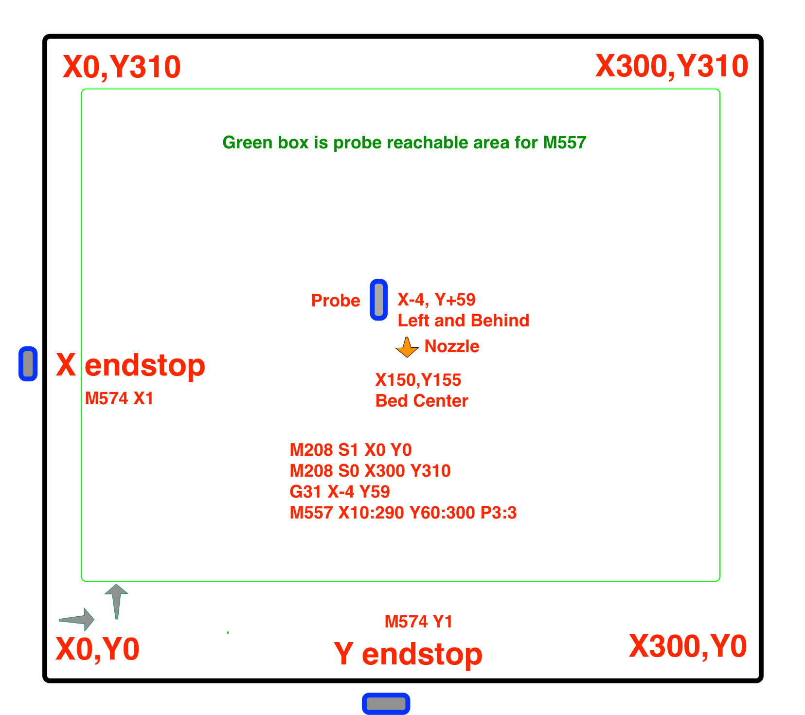
                                    Perhaps create an image like this to help you visuallise.

                                    Bed Area.png

                                    Z-Bot CoreXY Build | Thingiverse Profile

                                    1 Reply Last reply Reply Quote 0
                                    • lui2004undefined
                                      lui2004
                                      last edited by

                                      so now i have sorted out !
                                      probe is in the middle.

                                      but i have problems with the Z-offset:
                                      my procdure to set z-offset with duet wifi and BLtouch:

                                      1. G28 XY
                                        G1 X68.8 Y105.5 F4000 ; Move probe to middle of bed

                                      2. G30

                                      3. jog Z axis untill the nozzle is touching the bed

                                      4. G92 Z0

                                      5. up with G1 Z10

                                      6. G30 S-1

                                      7. i get the z-offset :
                                        G31 P25 X41.2 Y4.5 Z0.716

                                      if i start a print the nozle its to close to the bed

                                      is my procedure correctly ?

                                      Phaedruxundefined 1 Reply Last reply Reply Quote 0
                                      • Phaedruxundefined
                                        Phaedrux Moderator @lui2004
                                        last edited by

                                        @lui2004 said in help to setup M557 Mesh size:

                                        G31 P25 X41.2 Y4.5 Z0.716

                                        Your procedure sounds fine, but your probe is a bit far out in X, if there is some tilt in the bed or gantry the height difference between the nozzle and probe may start to matter.

                                        To try and correct for this it might help if you move the probe over so that it's right above where the nozzle was when you set Z0 before sending G30 S-1.

                                        Z-Bot CoreXY Build | Thingiverse Profile

                                        1 Reply Last reply Reply Quote 0
                                        • lui2004undefined
                                          lui2004
                                          last edited by

                                          so today i have made my first print X and Y Tensioner for my Ender 5 but it dont looks good the quality is not perfect !

                                          I have convert to DD with Bondtech Extruder and Micro Swiss all metal hotend.

                                          Filament is and Extruder are Calibrated.

                                          config.g

                                          ; Configuration file for Duet WiFi (firmware version 1.21)
                                          ; executed by the firmware on start-up
                                          ;
                                          ; generated by RepRapFirmware Configuration Tool v2 on Tue May 07 2019 23:06:50 GMT+0100 (British Summer Time)
                                          
                                          ; General preferences
                                          G90                                      ; Send absolute coordinates...
                                          M83                                      ; ...but relative extruder moves
                                          
                                          ; Network
                                          M550 P"Ender 5"                          ; Set machine name
                                          M552 S1                                  ; Enable network
                                          M586 P0 S1                               ; Enable HTTP
                                          M586 P1 S0                               ; Disable FTP
                                          M586 P2 S0                               ; Disable Telnet
                                          
                                          ; Drives
                                          M569 P0 S1                               ; Physical drive 0 goes forwards
                                          M569 P1 S1                               ; Physical drive 1 goes forwards
                                          M569 P2 S0                               ; Physical drive 2 goes backwards
                                          M569 P3 S0                               ; Physical drive 3 goes forwards
                                          M584 X0 Y1 Z2 E3                               ; set drive mapping
                                          M350 X16 Y16 Z16 E16 I1                 ; Configure microstepping with interpolation
                                          M92 X80 Y80 Z800 E497.82                ; Set steps per mm
                                          M566 X600.00 Y600.00 Z60.00 E300.00      ; Set maximum instantaneous speed changes (mm/min)
                                          M203 X6000.00 Y6000.00 Z500.00 E6000.00  ; Set maximum speeds (mm/min)
                                          M201 X500.00 Y500.00 Z100.00 E5000.00    ; Set accelerations (mm/s^2)
                                          M906 X500.00 Y600.00 Z500.00 E600.00 I30  ; Set motor currents (mA) and motor idle factor in per cent
                                          M84 S30                                  ; Set idle timeout
                                          
                                          ; Axis Limits
                                          M208 X0 Y0 Z0 S1                         ; Set axis minima
                                          M208 X220 Y220 Z300 S0                   ; Set axis maxima
                                          
                                          ; Endstops
                                          M574 X1 S1 P"xstop"                            ; configure active-high endstop for low end on X via pin xstop
                                          M574 Y1 S1 P"ystop"                            ; configure active-high endstop for low end on Y via pin ystop
                                          ;M574 Z1 S1 P"zstop"                            ; configure active-high endstop for low end on Z via pin zstop
                                          M574 Z0                                     ; configure Z-probe endstop for low end on Z
                                          
                                          M558 P9 C"^zprobe.in" H5 F100 T4000            ; set Z probe type to bltouch and the dive height + speeds
                                          M950 S0 C"exp.heater7"                         ; create servo pin 0 for BLTouch
                                          ;G31 P500 X41.2 Y-4.5 Z0.685                  ; set Z probe trigger value, offset and trigger height
                                          ;M557 X15:215 Y15:195 S20                       ; define mesh grid
                                          G31 P25 X41.2 Y4.5 Z0.716                    ; set Z probe trigger value, offset and trigger height
                                          M557 X41.2:221.2 Y4.5:219.5 S20                       ; define mesh grid
                                          
                                          
                                          ; Heaters
                                          M308 S0 P"bedtemp" Y"thermistor" T100000 B4138 ; configure sensor 0 as thermistor on pin bedtemp
                                          M950 H0 C"bedheat" T0                          ; create bed heater output on bedheat and map it to sensor 0
                                          M307 H0 B0 S1.00                               ; disable bang-bang mode for the bed heater and set PWM limit
                                          M140 H0                                        ; map heated bed to heater 0
                                          M143 H0 S120                                   ; set temperature limit for heater 0 to 120C
                                          M308 S1 P"e0temp" Y"thermistor" T100000 B3950  ; configure sensor 1 as thermistor on pin e0temp
                                          M950 H1 C"e0heat" T1                           ; create nozzle heater output on e0heat and map it to sensor 1
                                          M307 H1 B0 S1.00           
                                          
                                          ; Fans
                                          M950 F0 C"fan0" Q500                           ; create fan 0 on pin fan0 and set its frequency
                                          M106 P0 S0 H-1                                 ; set fan 0 value. Thermostatic control is turned off
                                          M950 F1 C"fan1" Q500                           ; create fan 1 on pin fan1 and set its frequency
                                          M106 P1 S1 H1 T45                              ; set fan 1 value. Thermostatic control is turned on
                                          
                                          ; Tools
                                          M563 P0 D0 H1                            ; Define tool 0
                                          G10 P0 X0 Y0 Z0                          ; Set tool 0 axis offsets
                                          G10 P0 R0 S0                             ; Set initial tool 0 active and standby temperatures to 0C
                                          
                                          ; Automatic saving after power loss is not enabled
                                          
                                          ; Custom settings are not configured
                                          M501
                                          M575 P1 S1 B57600
                                          

                                          Pictures from the printed Tensioner:

                                          teil.jpg
                                          teil (2).jpg
                                          teil (3).jpg
                                          teil (4).jpg

                                          Simplify3D Config:

                                          20200922_075339.jpg
                                          20200922_075346.jpg
                                          20200922_075348.jpg
                                          20200922_075352.jpg
                                          20200922_075356.jpg
                                          20200922_075407.jpg
                                          20200922_075411.jpg
                                          20200922_075414.jpg
                                          20200922_075418.jpg

                                          1 Reply Last reply Reply Quote 0
                                          • lui2004undefined
                                            lui2004
                                            last edited by

                                            neu.jpg

                                            neu1.jpg
                                            neu2.jpg
                                            neu3.jpg
                                            neu4.jpg

                                            1 Reply Last reply Reply Quote 0
                                            • First post
                                              Last post
                                            Unless otherwise noted, all forum content is licensed under CC-BY-SA