Random Smart Effector flashes
-
I have a Delta Predator , SKR 1.4T with Magballs and smart Effector with RRF , the smart effector after a reboot flashes 2 times all good and it does the auto delta calibration and then mesh level , and no problems , during a print or even after the print random the LED flashes as if its touching something , even though there is nothing , i reboot without touching anything it flashes 2 times and it work fine and then again i get this random , i checked so the far the followings :
1-fan noise
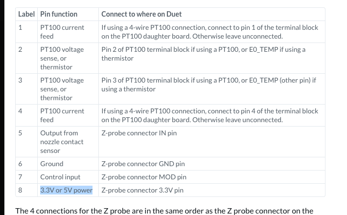
2-wire crimp of the wires on the 8 pin connectorsthe MOD connector is not connected , and the VCC is connected to the SWD 3.3 , it was connected to 5V which was on the Servos connector , as shown on the forum 3.3v or 5v
what do i need to do ?
-
It's completely normal for it to flash during prints and moves, part cooling fans can cause it to flash also mine for instance flashes constantly when printing or part cooling is on
as long as it calibrates fine there is no issue. -
No it flashes while its standing still and when this happen i get this output after the G32 , i know during printing its normal to flash but while standing still doing nothing ?!!
9/13/2020, 11:49:32 AM G32
Error: Z probe already triggered at start of probing move
Error: Z probe was not triggered during probing move
Error: Z probe was not triggered during probing move
Error: Z probe was not triggered during probing move
Error: Z probe was not triggered during probing move
Error: Z probe was not triggered during probing move
Error: Z probe was not triggered during probing move -
@sankafola
Error: Z probe already triggered at start of probing move
Normally caused by fan noise
or it's a bad crimp/solder joint either end -
but that are the 2 things i mentioned in my post which i checked and its not that
1-fan noise
2-wire crimp of the wires on the 8 pin connectorsanything else ?
-
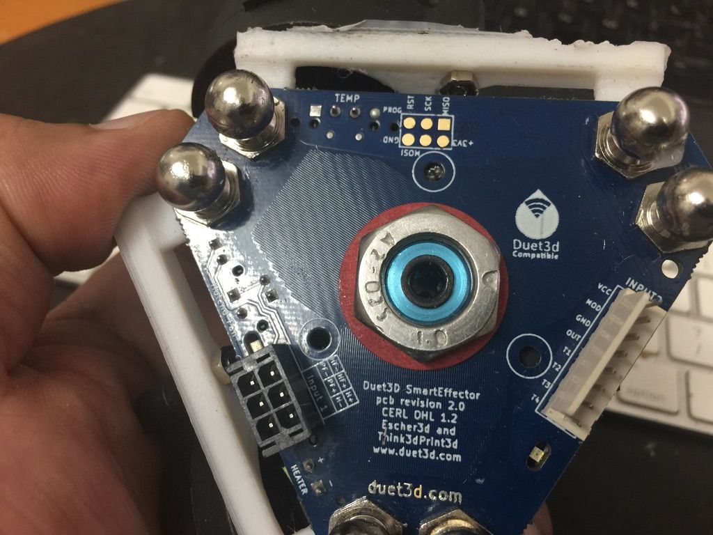
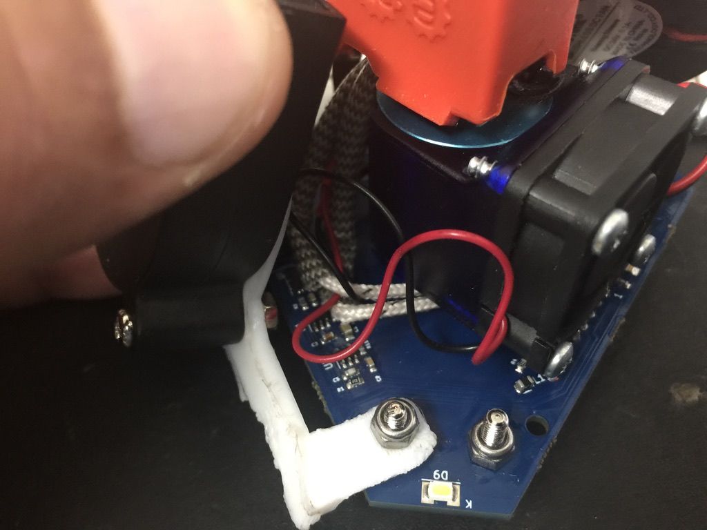
Give it the old disassemble and reassemble? While it's apart take some photos of both sides of the PCB for us to see?
-
sure here it is
-
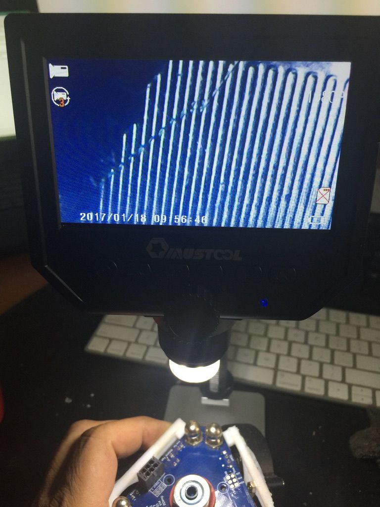
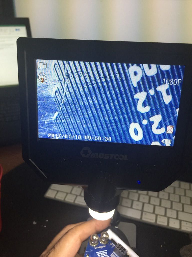
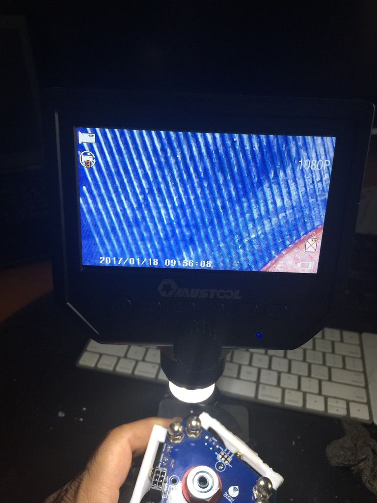
Is that a scuff on the traces of the strain gauge?
If you inspect the surface of the PCB closely do you see any scratches?
-
this is 60X
-
That does look like some damage.
-
that means i need to buy a new one or this can be fixed ?
-
@sankafola said in Random Smart Effector flashes:
or this can be fixed ?
depends on how handy you are with a soldering iron; you could try to take some abrasive to the area and abrade off the blue layer getting down to the copper traces and soldering some bridges across.
-
@bearer That's more optimistic than my answer was going to be.
-
@Phaedrux said in Random Smart Effector flashes:
@bearer That's more optimistic than my answer was going to be.
") i've been around too much bob the builder watching little people - the optimism seems to rubs off no matter how hard i try to resist!
i've been around too much bob the builder watching little people - the optimism seems to rubs off no matter how hard i try to resist!however no doubt about it, its fiddly work, but certainly possible.
-
this pic are x60 times the size , my iron is bigger than 2 lines no way to solder

-
@bearer the idea is to solder the cut off lines right /?
-
@sankafola said in Random Smart Effector flashes:
this pic are x60 times the size , my iron is bigger than 2 lines no way to solder
if its just a hairline break in the trace you'd probably be okay with some tacky flux and just dragging the tip across with a little solder on to bridge the gap; but some experience would help
-
if you have a meter you could try measuring the resistance across as shown on the back of the board? (power off)

-
you mean U3 ? and U1 ?
-
close up: (edit: maybe not having it mirrored helps..)
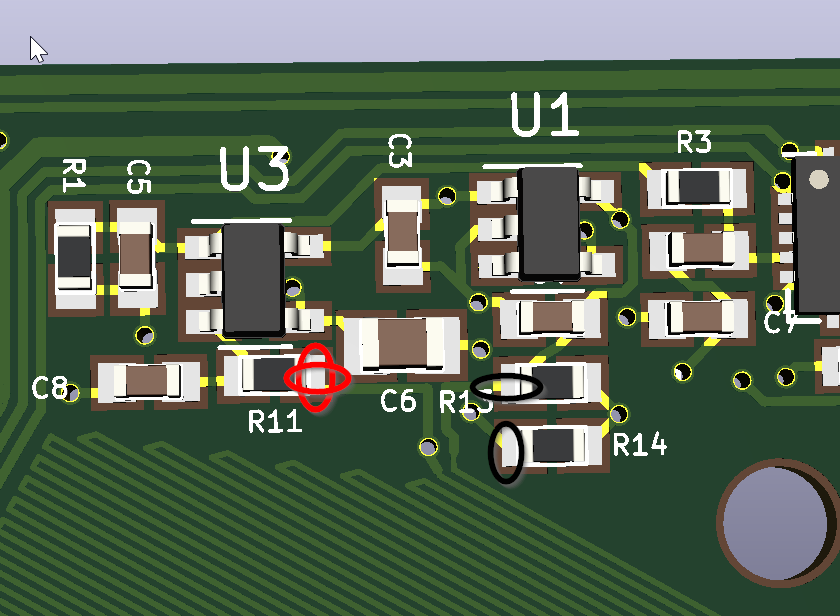
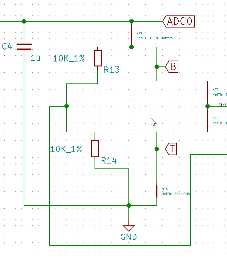
R11, and R14 as indicated by the tall elipses.
then compare to the other half of the bridge on R11 and R13 as indicated by the wide elipses?
B and T on the schematic are essientially
10kresistors in the form of PCB traces, and you're trying to measure if they are different: