I have a question when wiring the servo i/o link.
-
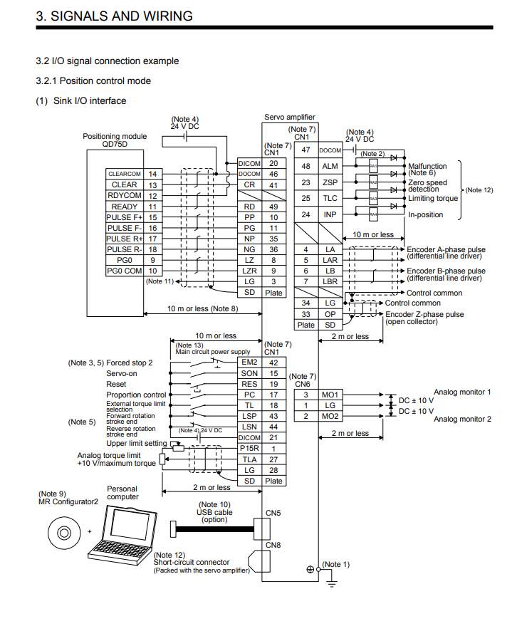
Looking at the i/0 link in the current position control mode, there are additionally LZ, LZR, DOCOM, RES, SON, and ALM in PP, PG, NP, NG, but only 4 lines can be connected to DUET 2 EXPANSION BOARD. Where should the rest of the I/O LINK lines be connected?

-
I assume you are connecting this to a Duet 2 Expansion Breakout Board?
We need more information on the dervo model (please link to the datasheet)
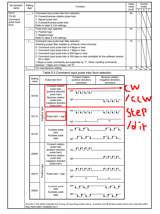
It looks like this interface uses a pulse forward, pulse backward type of connection (also sometime called CW/CCW - clockwise, counter-clockwise) The Duet outputs step pulses and a direction signal - which is different.
-

In the manual of MR-J4-100A, there is a parameter setting.
CW/CCW parameters and STEP/DIR parameters can be set.