G29 failing height map has a substantial Z offset
-
@Phaedrux
Did you steps; confirm no heatmap seen. ran g28 than g29; same error. Heatmap looks the same image url)
 -
@fcwilt
This is my M557 X45:282 Y46:254 P2:2 S240 S240; what should it look like for 150,150 (I just starting to lean rrf; from marlin and not expert in that either) -
@harlock328 said in G29 failing height map has a substantial Z offset:
@fcwilt
This is my M557 X45:282 Y46:254 P2:2 S240 S240; what should it look like for 150,150 (I just starting to lean rrf; from marlin and not expert in that either)For starters you use either Paa:bb or Saa:bb, not both.
Now you can use just Paa or Saa and it treats it as Paa:aa or Saa:aa, so I just use the aa:bb form.
As to testing with 9 points to be sure that the middle point is the same as 150,150 I think that this would work
M557 X50:250 Y50:250 S100:100
because 50 + 100 = 150 and 150 + 100 = 250.
I don't know what your probe X and Y offsets are, so remember to take them into account when moving the probe to 150,150 when using G30.
Frederick
Printers: a small Utilmaker style, a small CoreXY and a E3D MS/TC setup. Various hotends. Using Duet 3 hardware running 3.4.6
-
The files you are editing are in the /system folder, right?
Please send M98 P"config.g" and post the results.
If you got to the general tab in DWC, what version does it report as?
-
@Phaedrux
I put changes in config.user.g config.g says Do NOT make changes here and to modify config.userBoard: Duet WiFi 1.02 or later + DueX5
Firmware: RepRapFirmware for Duet 2 WiFi/Ethernet 2.05.1 (2020-02-09b1)
Duet WiFi Server Version: 1.23 -
I realize that, please send M98 P"config.g" in the gcode console and post the results.
For the DWC version please check under machine specific.
-
@Phaedrux
Talking about Duet Web Control? If so Duet Web Control 2.0.7 -
Yes thanks. Just trying to confirm that your version of DWC is compatible with your firmware version.
Running M98 P"config.g" will execute your config file and any other called macros and will echo any error messages to the gcode console that might otherwise get missed during the bootup process due to timing. I want to know if it's throwing any errors.
-
-
@harlock328 said in G29 failing height map has a substantial Z offset:
I put changes in config.user.g config.g says Do NOT make changes here and to modify config.user
I think you will find that you are better off combining those two into just config.g.
And keep related things together.
Frederick
-
Well this may be part of the problem.
Error: Bad command: M208 S1 Z-5 :set minimum Z travel
You can delete that command from the config files. It gets overwritten a few lines down anyway, so it doesn't have the intended effect anyway.
Still no smoking gun on why there is an offset.
The only thing that might be causing issues is the split M558 commands with some values spread all over the place, but that bug was in RRF3 and not RRF2.
At this point I would suggest backing up your config files and then creating a fresh basic config using the web configurator and testing with that. If that works correctly then we know the error is somewhere in the added complexity of your current config.
If this is a config provided by the railcore users, you may want to try checking with their discord chat to see what they think.
-
@Phaedrux said in G29 failing height map has a substantial Z offset:
Well this may be part of the problem....
In my experience the Z offset message occurs when all the points of the height map have a Z value significantly different from the Z value as determined by G30.
In this case he has probed the corners but has not included a point at or very near the point used with G30.
Which is why I suggested using a 9 points (3 by 3) such that the 5th point is at the same location as the "G30" point.
Frederick
-
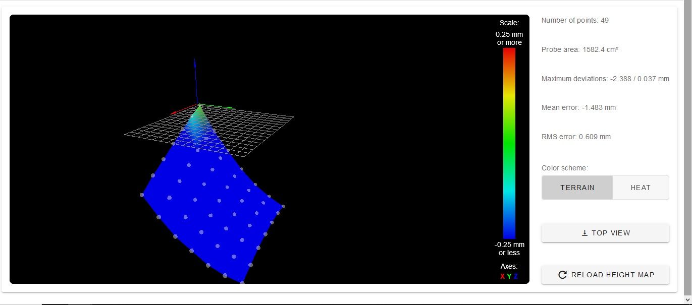
@fcwilt
This worked!!!")
Used M557 X45:282 Y46:254 P3:3
Ran G29; no error and below is heatmap

I like to thank everyone that was helping me.
-
@harlock328 said in G29 failing height map has a substantial Z offset:
@fcwilt
This worked!!!
Used M557 X45:282 Y46:254 P3:3Glad to here the problem has been found.
JOOC why are you using those X and Y values as apposed to round numbers, something like X50:280 Y50:260?
Thanks.
In any case now you can up the P parameters to place the points closer together, perhaps P20:20.
Frederick
-
@fcwilt
Magnet bed; numbers I found for others using 713 mag bed to avoid the mags when probing for railcore II. -
@harlock328 said in G29 failing height map has a substantial Z offset:
@fcwilt
Magnet bed; numbers I found for others using 713 mag bed to avoid the mags when probing for railcore II.Understood. I use the BuildTak FlexPlate system and it wrecked havoc with my 12mm inductive sensor at certain points.
If you had problems because of the magnets you may find that when you change to using P20:20 or similar they will crop up again.
Let us know.
Thanks.
Frederick
-
Hello everybody. I seem to have a similar problem with my z probe.I've run the G29 Mesh compensation, and the height map looks something like the pic bellow:
Now, the config.g is listed bellow:
; Configuration file for Duet WiFi (firmware version 3)
; executed by the firmware on start-up
;
; generated by RepRapFirmware Configuration Tool v3.1.4 on Mon Oct 05 2020 11:50:08 GMT+0300 (Eastern European Summer Time); General preferences
G90 ; send absolute coordinates...
M83 ; ...but relative extruder moves
M550 P"Oscar" ; set printer name
M669 K1 ; select CoreXY mode; Network
M551 P"" ; set password
M552 S1 ; enable network
M586 P0 S1 ; enable HTTP
M586 P1 S1 ; enable FTP
M586 P2 S0 ; disable Telnet; Drives
M584 X1 Y0 Z2 E3:4 ; set drive mapping; INIT:X=0; Y=1; Z2;E3:4
M569 P0 S0 ; physical drive 0 goes backwards
M569 P1 S0 ; physical drive 1 goes backwards
M569 P2 S1 ; physical drive 2 goes FORWARDS
M569 P3 S1 ; physical drive 3 goes FORWARDS
M569 P4 S0 ; physical drive 4 goes backwardsM350 X16 Y16 Z16:16 E16:16 I1 ; configure microstepping with interpolation ; INIT- M350 X16 Y16 Z16 E16:16 I1
M92 X160.00 Y160.00 Z3200.00 E881.10:881.10 ; set steps per mm
M566 X900.00 Y900.00 Z12.00 E120.00:120.00 ; set maximum instantaneous speed changes (mm/min)
M203 X6000.00 Y6000.00 Z360.00 E1200.00:1200.00 ; set maximum speeds (mm/min)
M201 X500.00 Y500.00 Z20.00 E250.00:250.00 ; set accelerations (mm/s^2)
M906 X1400 Y1400 Z1200 E1200:1200 I80 ; set motor currents (mA) and motor idle factor in per cent
M84 S30 ; Set idle timeout; Axis Limits
M208 X0 Y0 Z0 S1 ; set axis minima
M208 X600 Y600 Z525 S0 ; set axis maxima; Endstops
M574 X1 S1 P"!xstop" ; configure active-high endstop for low end on X via pin xstop -added "! to xstop"
M574 Y1 S1 P"!ystop" ; configure active-high endstop for low end on Y via pin ystop - added"! to xstop"
M574 Z1 S2 ; configure Z-probe endstop for low end on Z; Z-Probe
M950 S0 C"duex.pwm5" ; create servo pin 0 for BLTouch
M558 P9 C"^zprobe.in" H5 F120 T6000 ; set Z probe type to bltouch and the dive height + speeds
G31 P25 X10 Y10 Z3.5 ; set Z probe trigger value, offset and trigger height
M557 X15:470 Y15:470 S20 ; define mesh grid; Heaters
M308 S0 P"bedtemp" Y"thermistor" T100000 B4138 ; configure sensor 0 as thermistor on pin bedtemp
M950 H0 C"bedheat" T0 ; create bed heater output on bedheat and map it to sensor 0
M307 H0 B0 S1.00 ; disable bang-bang mode for the bed heater and set PWM limit
M140 H0 ; map heated bed to heater 0
M143 H0 S250 ; set temperature limit for heater 0 to 120C
M308 S1 P"e0temp" Y"thermistor" T100000 B4138 ; configure sensor 1 as thermistor on pin e0temp
M950 H1 C"e0heat" T1 ; create nozzle heater output on e0heat and map it to sensor 1
M307 H1 B0 S1.00 ; disable bang-bang mode for heater and set PWM limit
M308 S2 P"e1temp" Y"thermistor" T100000 B4138 ; configure sensor 2 as thermistor on pin e1temp
M950 H2 C"e1heat" T2 ; create nozzle heater output on e1heat and map it to sensor 2
M307 H2 B0 S1.00 ; disable bang-bang mode for heater and set PWM limit; Fans
M950 F0 C"fan0" Q500 ; create fan 0 on pin fan0 and set its frequency
M106 P0 S1 H-1 ; set fan 0 value. Thermostatic control is turned off
M950 F1 C"fan1" Q500 ; create fan 1 on pin fan1 and set its frequency
M106 P1 S1 H-1 ; set fan 1 value. Thermostatic control is turned off; Tools
M563 P0 S"Tool 1" D0 H1 F0 ; define tool 0
G10 P0 X0 Y0 Z0 ; set tool 0 axis offsets
G10 P0 R0 S0 ; set initial tool 0 active and standby temperatures to 0C
M563 P1 S"Tool 2" D1 H2 F0 ; define tool 1
G10 P1 X0 Y0 Z0 ; set tool 1 axis offsets
G10 P1 R0 S0 ; set initial tool 1 active and standby temperatures to 0C; Custom settings are not defined
M912 P0 S-16.95 ; adjustment of the MCU temp read; Miscellaneous
M575 P1 S1 B57600 ; enable support for PanelDue
M501 ; load saved parameters from non-volatile memory
M911 S10 R11 P"M913 X0 Y0 G91 M83 G1 Z3 E-5 F1000" ; set voltage thresholds and actions to run on power loss -
Hi,
It looks like your probe is working but your bed needs to be leveled.
What kind of printer is it? How is the bed mounted? Does the bed have leveling adjustments?
Frederick
-
@fcwilt The bed is fixed. Is it possible to compensate via the firmware? I had a look over the "Mesh bed compensation" documentation, I have a height map which how can I use it to make the proper height compensations, and those compensations can be made with the G32 command if the Z motors are connected to the board in series( ZA;ZB)?
-
Hi,
G29 and G32 are different things.
G29 is use for mesh compensation. You used it to create the height map you posted.
If mesh compensation is active then during printing the Z position is tweaked as needed, according to the height map, to better follow the surface of the bed.
G32 is used to run the macro file bed.g. The contents of this file determine what it does.
It can do the following:
-
calibrate a delta style printer.
-
if you have manual leveling adjustments on your bed, it can probe the bed and tell you how to turn each adjustment to level your bed.
-
if you have multiple Z steppers supporting your bed in such a way that they can be used to level the bed, it can probe the bed and adjust the steppers to level the bed.
You really need 3 steppers to level a bed, 2 can only adjust the tilt in one axis, likely side-to-side.
BUT in either case you have to have steppers connected to their own drivers. The two Z connections on the Duet share a driver and cannot be used for leveling.
Now if you only had one extruder you could use the other extruder connection for one of the two Z motors.
You can still use mesh compensation during printing.
Assuming you have an existing height map you only need to do two things at the start of a print.
- use a G30 command to probe the bed at (or very near) the center of the bed, this sets the Z=0 datum.
- use a G29 S1 command to load the existing height map and thus activate mesh compensation.
Some folks create the height map at the start of every print. In that case you simply use G29 rather the G29 S1. Creating the height map also activates mesh compensation, at least for the duration of the print.
Hope that helps.
Frederick
-