igus D1 motor controller + Expansion Board -- Step timings?
-
Hi all,
I'm building a bigger than usual 3D printer at the moment and would like to clear some things before moving along.
Setup:
Duet 2 Ethernet @ RRF 3.1.1 + Expansion Breakout Board
3x igus D1 motor controllers to drive NEMA23 Motors in closed loop setup (for X, Y, U axes)My question is how you would interpret the instructions from the manual regarding the options of M569.
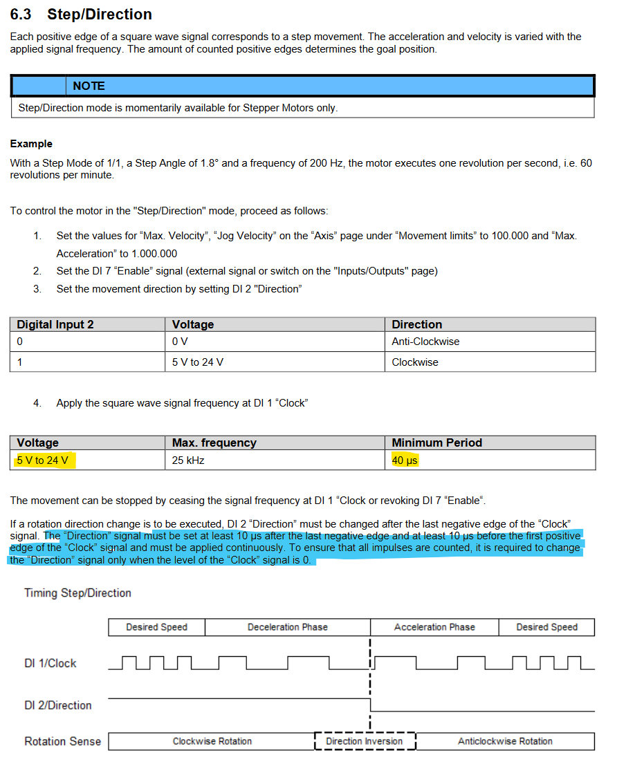
from the igus D1 manual, page 81:
- I assume I'll have to tweak the Expansion Breakout Board to deliver 5V on the respective Pins for the D1 to take the signals properly?
- How would I have to set up the M569 T parameter in order to meet the instructions?
from the documentation:
Minimum driver step pulse width, step pulse interval, direction setup time and direction hold time, in microsecondsMy uneducated guess:
- minimum pulse width = minimum period = 40µs
- step pulse interval = inverse of frequency = 40µs
- direction setup time = "10 µs after the last negative edge and 10 µs before the first positive edge" = 10µs
- hold time = infinite?
Any input would be appreciated. Please note that I didn't try to drive the motors with this setup yet, but plan to do so next week, so at this point we're talking hypothetically ...
Have a great weekend everyone!
best regards, Niklas
-
- they may work at the 4.x volts form the EBOB
- I think the step-to-direction hold time is a minimum of 10uS as well so try that.
-
@sonderzug said in igus D1 motor controller + Expansion Board -- Step timings?:
minimum pulse width = minimum period = 40µs
step pulse interval = inverse of frequency = 40µs
direction setup time = "10 µs after the last negative edge and 10 µs before the first positive edge" = 10µs
hold time = infinite?Try 20:20:10:10.
BTW, 25kHz is a low step frequency for a 3D printer. You may find it too low to get both good movement speed and good resolution.
-
Hello David and Tony,
thank you both for your input, I will try this as soon as possible.
Interesting mention about the low maximum frequency. I might discuss this with the developers of the igus controller. -
Hello Gentlemen,
I've had the chance today to play around with my setup today.
In regard to my questions above, I can report the following:- the igus controllers in fact seem to be happy with the "unadultered" output of the EBOB. They have a separate +5V/- input for logic level connection with external controllers such as the Duet, which I connected to the same 5V/3A PSU as the Duet itself. Accordingly I've only connected the S-, D-, and E- pins to the respective inputs of the igus D1.
- I've gone with the recommended setting of M569 P5 T20:20:10:10 which in turn seems to work fine. I've not tried to go any lower yet (is anyone interested in this experiment?)
- regarding resolution, I've set the Duet and igus D1 up at 1/32 stepping at the moment. Considering the 20T HTD 3 mm pulleys I am using resulting in ~ 106 steps/mm and at 25 kHz max. step frequency this gives about 235 mm/s in movement speed which is totally acceptable. Moving the one motor I'm experimenting with seems to work even at higher speeds. We will see in the final application how well this works.
thank you again for your support.
Best regards, Niklas