Duet 2: using Z brake
-
Hi,
I have been trying to find a brake principe for my belt driven Z axis for a while now.
On the reprapforums someone adviced using a relay to short the 2 phases of a Nema stepper motor. I am just wondering how i should connect this to my Duet2 wifi board (i am aware this will void warranty). I was also informed the braking might not last long on a long and heavy Z axis (45 cm and +-5kg)Can anyone advice me how to connect this for a duet2 instead of a MKS board?
Thanks in advance. For all interested, the info is on a russian link, just translate the page.
https://3dtoday.ru/blogs/3dmaniack/sistema-tormozheniya-shd-posle-ego-otklyucheniya-v-2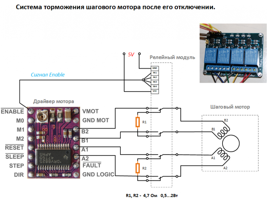
-
I think @oozeBot may have implemented something like this z brake.
-
Yes I did do this in an early prototype but we've now removed it as we found a way to better counter balance the gantry where it is no longer needed..
Here is the only photo I have of it currently. It takes two relays per stepper.

-
Hi,
I "solved" that problem, on my printer, by using 2mm pitch lead screws.
Movement at the same speed as an 8 pitch lead screws requires faster stepper speed (4x) and it is rather noisy.
But for normal Z speeds it's just fine.
Frederick
-
@TheGov said in Duet 2: using:
On the reprapforums someone adviced using a relay to short the 2 phases of a Nema stepper motor. I am just wondering how i should connect this to my Duet2 wifi board (i am aware this will void warranty). I was also informed the braking might not last long on a long and heavy Z axis (45 cm and +-5kg)
Can anyone advice me how to connect this for a duet2 instead of a MKS board?You can do it in the same way for a Duet. You don't need the 4.7 ohm resistors, you can use the relays to short the windings.
You can simplify the circuit by switching only one wire from each stepper motor phase, so you only need two SPDT relays (or one DPDT relay) per motor.
To reduce the risk of damage to the drivers on the Duet, use the
M918M911 command to execute M18 when a power loss is detected, to turn the motors off. With luck the motor currents will have dropped to near zero by the time the relay changes over.Note, shorting the motors is unlikely to stop them turning, but it will slow them down.
Duet WiFi hardware designer and firmware engineer
Please do not ask me for Duet support via PM or email, use the forum
http://www.escher3d.com, https://miscsolutions.wordpress.com -
Thank you everyone for the responses!
@dc42 , Great forum and suppport you have going on here.
I have the same relay as mentioned in the plan it's this one.
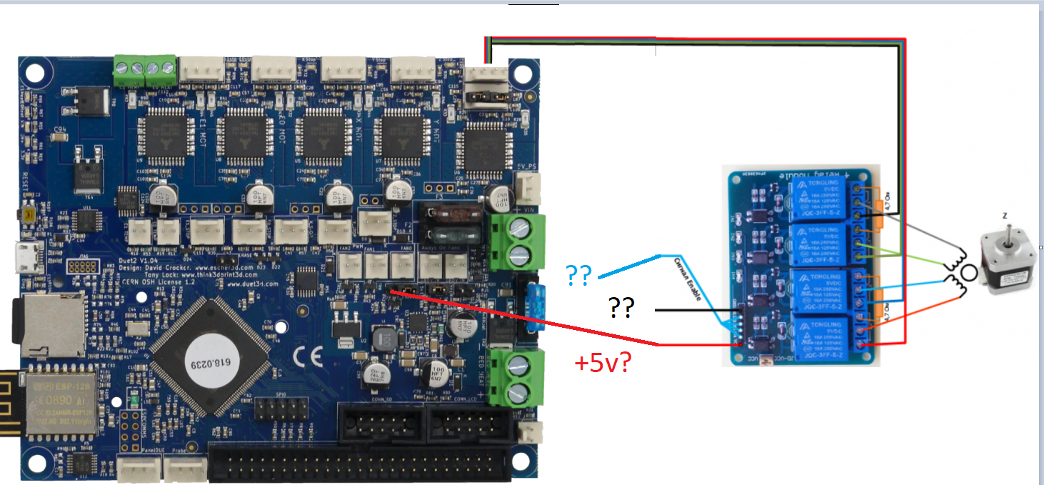
https://www.aliexpress.com/item/32760607353.html?spm=a2g0s.9042311.0.0.27424c4dJsEquuI made a plan, could you be so kind to make some simple changes to the plan? i used MS paint.
That would be very kind! I can see how to connect the motor part, i won't use any resistors like you mentioned but i am not sure how to connect the other side of the relay thoughThanks in advance
-
@dc42 said in Duet 2: using:
To reduce the risk of damage to the drivers on the Duet, use the M918 command to execute M18 when a power loss is detected, to turn the motors off.
David, can you elaborate on this? I've reviewed the M918 command and can't decipher how that can be used in connection with the M18?
-
@oozeBot I think he meant M911 for configuring what happens during power loss.
https://duet3d.dozuki.com/Wiki/Gcode#Section_M911_Configure_auto_save_on_loss_of_power That's where the M18 would go.
-
Is there anyone who can help me with my previous post?
Help is very much appreciated, it is basically my last step before i can start testing my printer which has been in development for the last 3 years. -
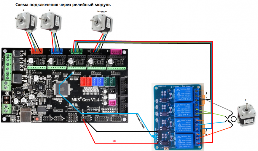
I updated the drawing
Can someone confirm this is the way to go?
Thanks
-
@TheGov I’m not sure if anyone wants to take the liability of telling you, for sure, that’s correct.. However, I did find another photo you could use to compare it to..
Note- I only used two relays per stepper where you are using four..

-
One more:

-
Thanks for the pictures.
Not really relevant for me i am afraid.Today i connected the relay like seen below, Z motor not working.
Relay also does not seem to be turned on, no short on coils when power is turned off either.
-
Have you considered using a simple mechanical brake ?
Below is what is essentially used on a large industrial cutting machine that has knives loaded on the z Axis . (its a cutter I have worked on)
During initialization of the cutting heads the cams turn counter clockwise releasing pressure on the solenoid that is powered by the DC power supply and it pulls out of the way . Z can now work in both directions . On any loss of power the solenoid drops out and catches the pawl in an 1/8th of a turn preventing the knives dropping into the table. Its a simple reliable system . Occasionally the solenoids fail , in 10 years over a 100 machines maybe 4 have been replaced. 3 burned out and 1 had some dirt /debris stopping it from engaging the pawl
-
Thx for the input, i actually have been think about this.
I bought a small solenoid for this purpose but was not able to get it working, possibly i was/am not thinking of a good implementation.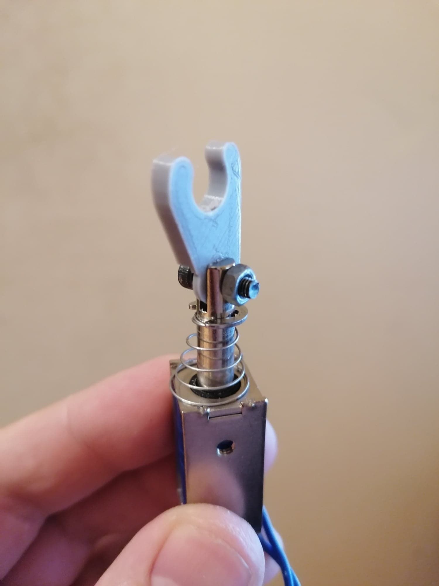
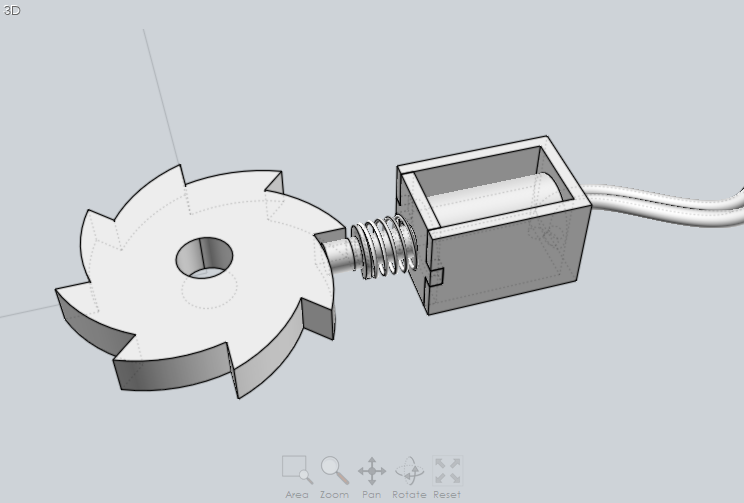
This is how my Z axis is driven, my solenoid design was not able to hold the axis, which made sense as soon as i tried it. Maybe you have a different idea how to implement the solenoid?

-
I also want to state that i have spare duet (partly faulty) to do the testing on..
Just would like to know what i'm doing wrong. -
If I had to design a brake for that Z axis I would mount the solenoid on that rail the motor is attached to and then have the Pawl on the left shaft . Design and print a Pawl cam and mate it to a GT2 20 or 30 tooth sprocket that has grub screws to fix it to the shaft and design and print an interference tooth for the end of the solenoid . Since its all plastic I would use surface areas as wide as possible . Its just a rough idea but I would attempt something like this
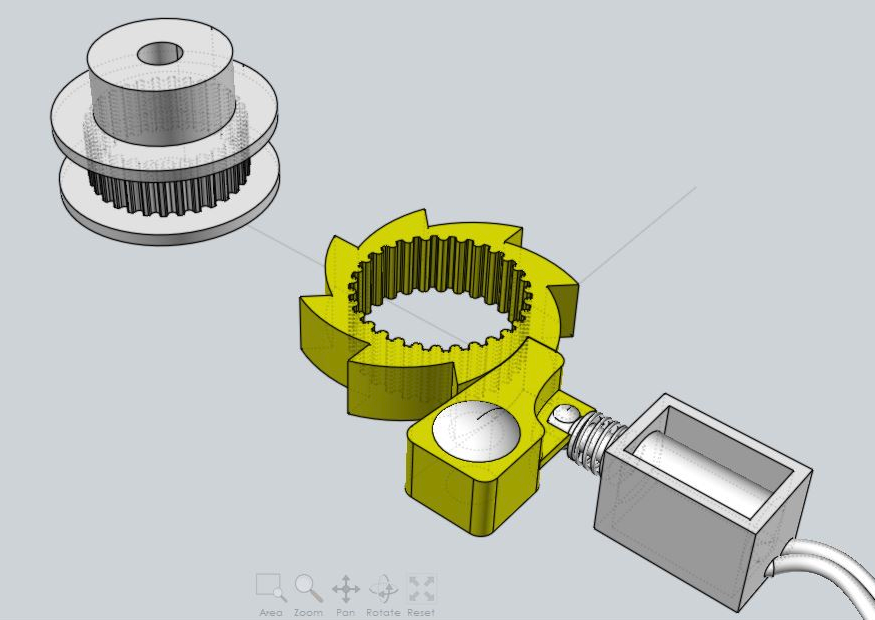
those flanges for the GT pulley apparently are not that hard to take off and put back on again once that printed piece is fitted on
-
 undefined JayT referenced this topic