@jay_s_uk : ok got it. you can mark this thread as Solved.
Thank you again!
Best posts made by JayT
-
RE: Configure dual extruder via expansion boardposted in General Discussion
-
RE: Shifting Issue After Resuming APF in RRFposted in Beta Firmware
I have one machine on Duet3. I flashed 3.5RC4. after this extruder motor holds the torque but does not move on extrude commands. When i go back to 3.4.6, it extrudes fine. looks similar to what she's reported. Mine is dual extruder.
Can anyone confirm that 3.5RC4 with their system:
a) drives dual extruder fine
b) Can you test Resume after power failure & check if it resumes fine & does not print from an offset. (for me it occurs in Y direction only).
This happens with Duet2 wifi based belt driven machine.c) Can anyone suggest a few checkpoints ?
-
RE: Configure dual extruder via expansion boardposted in General Discussion
I have attached the config file.
NOTE:- IF I run M115 B40 or M115 B41, I get positive response. both communicate well & the LEDs blinking is in sync. Same 3.4 beta3 on all boards.
- Also I noticed, if I configure single board with B40 address and run the second extruder it works. So this confirms no problem with second motor or the board. Something in config is weird?
- I haven't used G4 commands.
NOTE: config is too raw, just for trial purpose. main purpose is to try running dual extruder via exp- 1XDs. - B40 (no jumpers), B41-XD : jumper on CAN-FD-OUT.
Mainboard to B40 in -> B40 out -> B41-in-> Jumper on the B41-out. - I tried removing all jumpers too to see just in case it works.
(not able to upload file , so pasted images of the config).
-
RE: Shifting Issue After Resuming APF in RRFposted in Beta Firmware
@JayT :
This problem of extruder not working with Duet 3 is resolved after flashing RRF3.5.1.
Shifting problem remains same with Duet2, after resume on power failure. -
RE: Simulated time turns N/A before print endsposted in General Discussion
@JayT
@dc42 : After few trials, we confirmed that since timer (job duration & the decrementing simulation time) starts immediately after pressing Print. Here if the bed & extruder temperatures are not attended yet, the warmup duration accounts only for bed heater time to attain target temperature. Extruder time to attain temperature is not accounted.
Hence we reach to condition (t<0) and simulated time completes displays N/A, while print is still running for few minutes.2 methods to resolve this:
- We account extruder temperature also in warm up duration
- we start simulated time once Print actually starts (after warm up of bed & extruder)
What do you suggest ?
Do we evaluate time to attain extruder target temperature? Can you direct us to the code to change? -
RE: Gap in printing concentric circles-(CW side)posted in General Discussion
@modl :
Seam is not the issue. If we change this, it does not reduce gap.
Backlash does though. But even then I see the flatness at the top & bottom surfaces of the circle.I also observed very less similar flatness in left & right most sides of the circle. Is this due to some slippage?
Latest posts made by JayT
-
RE: Ringing in Y axis (Linear guide system, coreXY design)posted in General Discussion
@dc42 :
Hi David, I still see enough ringing despite using ZVDD& ZVDDD modes, but none reduce the ringing much. What am I missing here? The best frequency that works 20Hz with EI2 mode. But i still see lines on the plane Y facet.
Can you suggest what can be optimized in Settings or the design to eliminate this ringing in Y direction?
With cartesian i was able to solve ringing but could never attain acceleration > 800mm/s2 & speed >100. Same is the case with coreXY as well. I am not able to move to higher acceleration or speed.P.S.:
- I tried 0.9 degree double stack as well
- ZVD ZVDDD modes with 20Hz frequency.
-
RE: Ringing in Y axis (Linear guide system, coreXY design)posted in General Discussion
Below is result at 20-22Hz frequency, where many lines reduce, speed is 60mm/s, so the lines are closer. However, I am not able to remove these lines in the picture.
How do I capture this frequency in input shaping method?
This is with damping factor 0.05 though, with 0.01 lines are more prominent i felt.

-
RE: Ringing in Y axis (Linear guide system, coreXY design)posted in General Discussion
Hi Jay, I tried 20Hz, result was better. And I used following accelerometer curve to detect the exact frequency. as per this 27.4 shaper frequency, but that does not remove ringing for me like 20Hz. Can you suggest further on how to proceed here or how to analyze this graph?
Also What is the role of damping factor ? At 20Hz with 0.05 i get better result I feel. but I need to find proper frequency & damping factor to make its smooth.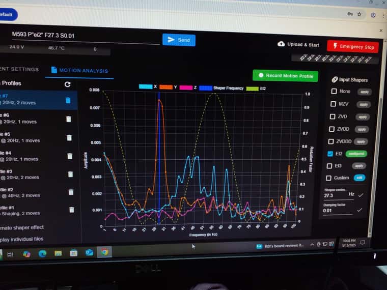
Damping factor 0.01
EI2
Mounted above BLtouch mount. -
RE: Ringing in Y axis (Linear guide system, coreXY design)posted in General Discussion
@jay_s_uk :
@dc42 :
Thank you for suggestions. I used EI2 & EI3 methods input shaping modes with 20Hz, and it indeed reduced ringing, also with reduced print speed, it further goes down. I am reading on connecting accelerometer to find exact frequency.Can you suggest where should I fit my accelerometer for Y-Axis? (on the extruder ? ) , NOTE: The accelerometer doesn't have axis marked.
Can you mark in the picture above to suggest? -
RE: Ringing in Y axis (Linear guide system, coreXY design)posted in General Discussion
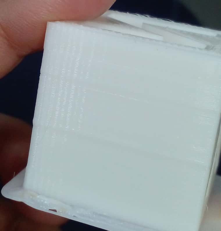
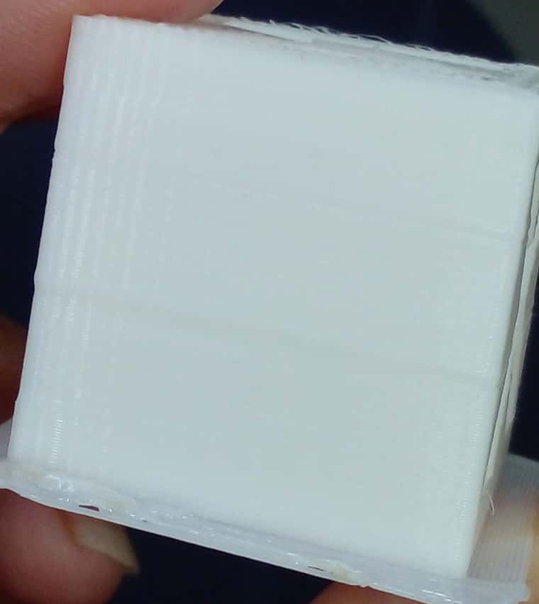
- Based on suggestion, I tried latest firmware 3.6 RC3.
NOTE: Tool head is Biqu. (not much heavy, with 3dpinted ducts for part cooling). - Attached is an image with the top one printed using DAA & bottom one is how base printing without DAA appears. There is absolutely no difference after input shaping. (I manually calculated distance between 2 lines using vernier (except the corner one) ).

- Jerk is 5.
- DAA: speed is 120mm/s, acceleration 800mm/s2, and distance is 2mm between 2 lines, so that 60Hz for DAA. We used ZVD mode.
- In the top cube, I also modified acceleration to 1500 mm/s2, but no difference.
Can you suggest here further?
- Based on suggestion, I tried latest firmware 3.6 RC3.
-
RE: Ringing in Y axis (Linear guide system, coreXY design)posted in General Discussion
YEs, we initially used 2000mA, reduced it down to 1600mA.
- Tried to use Pulse dir pins with external driver as well. no luck.
- I am using 0.9deg motors (as with 1.8degree there was vertical ribbing in Y axis).
- I had built cartesian system, even then Y always had ringing. this wasn't the problem with 300bed side. Then we moved to Corexy for 500 bed size, but ringing appear despite slow speeds.
-
RE: Ringing in Y axis (Linear guide system, coreXY design)posted in General Discussion
@jay_s_uk : Ok Let me try that. Meanwhile can you tell me if this is common in Linear guide systems? Any suggestion to check on design side?
-
RE: Ringing in Y axis (Linear guide system, coreXY design)posted in General Discussion
@jay_s_uk said in Ringing in Y axis (Linear guide system, coreXY design):
3.6-RC3
Motion shaping as in acceleration profile ? (I am not using input shaping, as it didn't give much results).
Do you see this problem arising from acceleration/deceleration profile ? -
RE: Ringing in Y axis (Linear guide system, coreXY design)posted in General Discussion
@jay_s_uk : RRF3.5.0 RC3.
NOTE: I use the same in 300 bed sized machine. It's not giving any problems.
-
Ringing in Y axis (Linear guide system, coreXY design)posted in General Discussion
Hi,
I am using Duet2 board, with corexy system of 500*500 build size. When I print, I see ringing effect only on Y-axis. Tried following solutions, but none worked.
- Tried with jerk values 1, 2, 3... upto 10 (acceleration 500, speed 60mm/s)
- Tried Different acceleration values from 500mm/s2 to 2500mm/s2 (speed 60mm/s & jerk 2)
- **Tightened the belts.
- Tried to double check alignment.
- Also tried DAA, but in vain.**
- Tried to use extra channels of Pulse & dir & use external drivers.
a) Can you suggest what can be done to find root cause of ringing & resolve problem here?
X axis is fine, its the Yaxis with the problem. Both on Linear guides, & Biqu extruder mounted.
b) If it is vibrations, How do I root down the problem.NOTE: I am also using ssame board on a smaller bed size, with guide rod mechanism & cartesian system, it worked fine.
Iin bigger size, rods induced vibrations, so I tried with corexy build to get better speeds.Images of ringing in XYZ cube: (ringing is always during breaking as per my observation)

Image of setup (top view)
