Duet3 BLTOUCH3.1 Probe deploys but doesn't trigger on Z Home
-
@Thalios yeah - M401 / M402 both deploy/retract.
I'll try G30. I've been clicking HOME Z in the DWC UI with the following in homez.g
; homez.g
; called to home the Z axis
;
; generated by RepRapFirmware Configuration Tool v3.1.4 on Tue Oct 20 2020 23:24:46 GMT+0800 (Australian Western Standard Time)G91 ; relative positioning
G1 H2 Z5 F6000 ; lift Z relative to current positionG90 ; absolute positioning
G1 X250 Y250 F6000 ; go to first probe point
G30 ; home Z by probing the bed; Uncomment the following lines to lift Z after probing
;G91 ; relative positioning
;G1 Z5 F100 ; lift Z relative to current position
;G90 ; absolute positioning -
@Phaedrux definitely looks like I should be testing with G10 not G28 Z

-
Well G28 Z calls homez and your homez contains a move to position the probe and then does a G30 to probe the bed, so that's a fine way to test.
-
-
actually, my deployprobe.g has:
M280 P0 S10 ; deploy BLTouchand retract:
M280 P0 S90 -
@Thalios - ditto for me too. Same commands in deploy/retract.
-
@Thalios out of interest - what is your printer spec? Home design/build?
Mine is Rat Rig VCORE pro / linear rails / triple z screws.
Volcano hot end, titan aero extruder.Interested to know for when I do finally reach bed calibration.
-
Railcore II 300ZL fully upgraded, duet 3 6HC, enclosure, E3D V6 Gold because I prefer it to the Mosquito.
I have a D3 on a Ender 3 Pro and a Tronxy X5SA-500 Pro. I have a Duet 2 Wifi on a frankenstein Tevo Tarantula that I home built to 330x330x300 with E3D V6. I'm waiting on the Duet 3 mini to go in my other Ender 3 Pro.
-
@vistalert said in Duet3 BLTOUCH3.1 Probe deploys but doesn't trigger on Z Home:
G30 same outcome, bed doesn't stop.
I'd be inclined to connect the BLtouch directly to the board pins without extension and test on the bench (keeping the bltouch vertical) to see if it's in fact a poor connection with the white trigger signal wire.
-
I was looking at your Config.g file.
2 things I see different from mine:
You have a endstop configured for Z. Can you try to take that off? (M574 Z1 S2)
and the "^" in the probe type (M558).
Just to see if that solves it.
-
Did you do a full continuity test from the multipin connector on the BLtouch all the way to the connector on the board to see if it follows through on all pins with no shorts?
-
@Phaedrux said in Duet3 BLTOUCH3.1 Probe deploys but doesn't trigger on Z Home:
I'd be inclined to connect the BLtouch directly to the board pins
he cant, he broke the original connector. he posted a picture of his fixed connector in the beginning of the thread.
-
@Veti said in Duet3 BLTOUCH3.1 Probe deploys but doesn't trigger on Z Home:
@Phaedrux said in Duet3 BLTOUCH3.1 Probe deploys but doesn't trigger on Z Home:
I'd be inclined to connect the BLtouch directly to the board pins
he cant, he broke the original connector. he posted a picture of his fixed connector in the beginning of the thread.
Oh right. Forgot about that. It's one long thread of many.
-
You actually can't connect the original connector to the D3. It's a group of 3, ground/yellow/white, then a group of two +v/ground. The D3 io pins require that the default connectors be removed so the wires can be organised to match the io pins.
-
@Phaedrux @Thalios @Veti - actually I did learn a very important lesson which I overlooked, and was flagged just now, and that's bench test all the components before you build. I could have spotted any potential issue with the BL Touch much sooner.
For now I'm settled on a couple more actions:
-
If I can get super motivated, I'll unmount the BLT get it connected to D3 on a bench and see if I can probe the BLT output with my little USB oscilloscope. This would prove beyond doubt that the BLT is providing an output or not.
-
Prove the ioports by configuring them as a switch endstop and check they report being triggered when I pull up the input pin.
-
If after all this the BLT is providing an output and all my ioports are good then I have only two possibilities ...either dodgy cable/connections, or interference.
The main thing dissuading me that it's a wiring issue is simply that I've done many continuity checks all the way from the BLT PCB to the D3 PCB. As I'm using twisted pairs, I'm also inclined to believe interference isn't the culprit.
This kinda sums up where we are. Of course, I'm also pending delivery of another BL Touch 3.1.
Fun days ahead!

-
-
@Phaedrux @Thalios Some exciting input:
- Update in my installation...I had a connector at the BL Touch end so I can easily disconnect my entire wiring harness at the hot end - i.e. disconnect thermistor, fans, heater and bltouch, with each having it's own connect.
My observation here is my connector at that location was completely redundant, because of course, the BL Touch has it's own removable connector if I needed it.
So I have now removed that connector you may have seen at the start of the thread, soldered and insulated each wire from BL touch running to the D3 (io5).
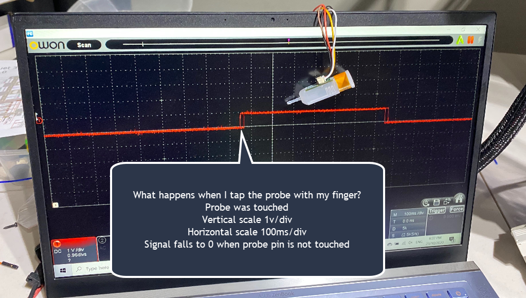
- I've got the BL Touch off the printer, and attached the BL Touch output to my hobbyist USB scope.
I have the scope set to 1V divisions in DC mode, and timebase is 100ms / division.
I execute M401 and the probe deploys.
I can then periodically touch the probe.
The scope clearly shows a signal out of the BL Touch 3.1 going from 0v, to +1v, every single time I touch it. When I release, it falls back to 0. This seems to indicate the output of the BLTouch is a simple hi/lo to indicate that something is contact with the probe. There is no PWM like signal back.The question now might be, is +1V enough to constitute logic 1 on the D3, when the BLT is powered with +5v?
This leads me to my next test. Issue G30 and then apply +5v to io5.in, and see if that emulates a probe trigger with a voltage which is certainly high enough to hold the input pin HI.
-
In this image you see the scope indicating that whenever the probe pin is touched, the BL touch outputs a higher voltage, and when released it falls.

-
are you touching the probe while the pin is retracted?
maybe you need to adjust the grub screw a bit higher as the pin is not making enough contact with the hall sensor. -
It's fixed!!!


It's a logic level issue as indicated in the 3.1 docs.
ref: https://www.antclabs.com/logic
Step 1: Connect the 3pin (brown, red, orange) and 2pin (black, white) to the control board.
Step 2: M280 P0 S10 ← least 500ms
Step 3: M280 P0 S140 ← least 100ms
Step 4: M280 P0 S130 ← least 500ms
Step 5: Pull the push-pin with your finger so that the red LED turns off.
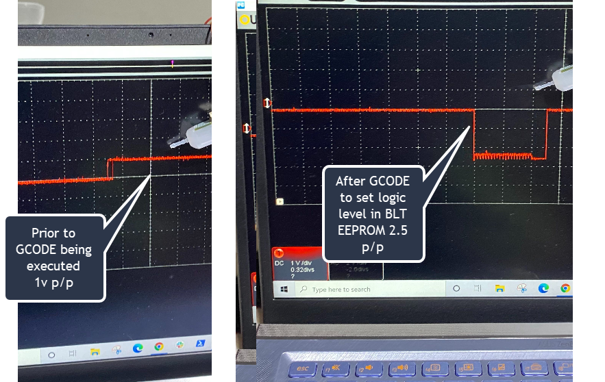
Step 6: M280 P0 S140 ← least 100msOnce I've executed this GCODE I then see much large voltage rage, hi to lo. Will post an image in a moment.
Having executed the GCODE, I do HOME Z, and when I then touch the probe the bed retracts!!

I'm slightly happy and excited to be past this one.
Thank you @Veti for being patient with me, and apologies again for that unwarranted tone half way through the thread.
Thank you @Phaedrux and @Thalios for the input and suggestions that got me here.
Back in a moment with an image to show the scope output after the GCODE above was executed. I'll do a full power cycle and ensure this config is retained by the EEPROM in the BLT.
-

Indicates the higher voltage applied to io.in, after the BLTOUCH is set for the new logical level