Inconsistent results with optical encoder wheel filament sensor
-
I am not sure ST alone will be a solution with a bounce so long. I think a comparator is something you'd wanna add here with ne555 circuit for proper debouncing ... on the other hand, instead of all that you could use some attiny44 or pic12f508 or something similar and make programmable debouncing circuit that one would embed in the sensor... in that case you could see what's the output of the laser/magnet sensor as they communicate with duet instead of just sending pulses
-
@JohnOCFII I think adding a "sample frequency" parameter to the filament motion sensing code would be useful to the largest number of people.
I'll download the code and see if I can make any suggestions there.
-
@alankilian said in Inconsistent results with optical encoder wheel filament sensor:
@JohnOCFII I think adding a "sample frequency" parameter to the filament motion sensing code would be useful to the largest number of people.
I'll download the code and see if I can make any suggestions there.
As I mentioned WAY up thread, I think all we really need to know is "is the wheel turning?" If yes, assume everything is fine. If no, tell the Duet to pause. Only variable is how long does the state of "not turning" need to be present before pausing?
John
-
@JohnOCFII Can you just set the "Over" amount to a huge value?
-
@alankilian said in Inconsistent results with optical encoder wheel filament sensor:
@JohnOCFII Can you just set the "Over" amount to a huge value?
Hmm... Perhaps.
Here's another odd data point. The two very first runs I did were within 200%. After than, I had days of testing where it would go from 30% to 3000%. But then, I started seeing those crazy high numbers, we'll above 10,000%. I do wonder if I'm chasing multiple issues.
-
@JohnOCFII Is this the wheel that you have applies the sticky copper tape to and cut out windows?
The sharper the windows are, the better results you'll get.
You might also try taping copper tape to both the emitter and receiver and only have a narrow (1/16 inch) slot in the copper cover. That and a narrow (1/16 inch) opening windows in the encoder wheel might help.
-
@alankilian said in Inconsistent results with optical encoder wheel filament sensor:
@JohnOCFII Is this the wheel that you have applies the sticky copper tape to and cut out windows?
The sharper the windows are, the better results you'll get.
You might also try taping copper tape to both the emitter and receiver and only have a narrow (1/16 inch) slot in the copper cover. That and a narrow (1/16 inch) opening windows in the encoder wheel might help.
It is. It seemed that that test didn't change results, leading me to believe the regular printed wheel was doing an acceptable job of breaking the light beam. Perhaps I switch back to an encoder wheel without the copper tape. I could also move back to the wheel with more spokes (the one on the right in this photo).

-
@JohnOCFII you can try other wheels, problem is just how the edge is created by that endstop and how it is interpretted by the duet... since there's obviously no signal conditioning from endstop and since it looks like duet is not doing any software debounce easiest thing would be to create a debounce circuit on the input
-
@arhi said in Inconsistent results with optical encoder wheel filament sensor:
@JohnOCFII you can try other wheels, problem is just how the edge is created by that endstop and how it is interpretted by the duet... since there's obviously no signal conditioning from endstop and since it looks like duet is not doing any software debounce easiest thing would be to create a debounce circuit on the input
Yes, creating the debounce circuit seems like a very useful thing to do.
-
@JohnOCFII What version are you running?
I can make a test build with a "Filter-time" parameter in the setup that ignores multiple edges for a minimum time before counting progress again.
I think you could set the time to 0.2 Seconds and you'd then get good results.
How fast were you extruding compared to the range of extrusion speeds you expect to use?
-
@JohnOCFII Or I could make you a test build with a new filament sensor type that says: "Filament is present if I get an edge at least every <Q> millimeters of filament when extruding."
-
@alankilian said in Inconsistent results with optical encoder wheel filament sensor:
@JohnOCFII What version are you running?
Board: Duet 2 Ethernet (2Ethernet)
Firmware: RepRapFirmware for Duet 2 WiFi/Ethernet 3.1.1 (2020-05-19b2)I can make a test build with a "Filter-time" parameter in the setup that ignores multiple edges for a minimum time before counting progress again.
I think you could set the time to 0.2 Seconds and you'd then get good results.
How fast were you extruding compared to the range of extrusion speeds you expect to use?
That capture was made at 15mm/sec. My standard profile goes up to 150mm/sec for infill.
-
@alankilian said in Inconsistent results with optical encoder wheel filament sensor:
@JohnOCFII Or I could make you a test build with a new filament sensor type that says: "Filament is present if I get an edge at least every <Q> millimeters of filament when extruding."
Hmm... Yes, that might be the most straightforward thing to try.
-
bouncing is 70-100ms .. that's long, but if that analog capture is any good the signal is actually pretty straightforward and just using ST as mentioned by @alankilian might solve 99% of the issues ... it will not solve them all, but if that analog part is true ST will get it to usable state.
74LVT14
power with 3v3, output will be 0/3v3, and input is 5V tolerable (actually survives up to 7V)
-
you are using connlcd3 or ENC_B and that's from what I see PC7 pin
from the datasheet
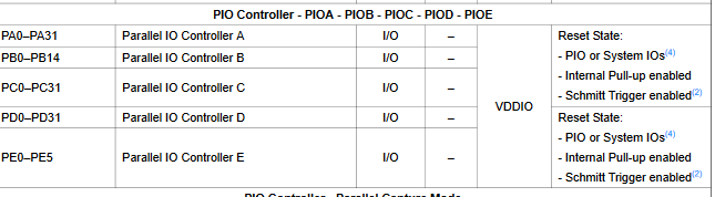
I think PC7 can be configured and Schmitt input directly in the firmware. I can't find here if we can configure pin as Schmitt input by addingt something to the name like we can for invert and pullup. IMHO any endstop input should be configured with Schmitt input, dunno if it is or not...
-
@arhi said in Inconsistent results with optical encoder wheel filament sensor:
you are using connlcd3 or ENC_B and that's from what I see PC7 pin
IMHO any endstop input should be configured with Schmitt input, dunno if it is or not...
I'm thinking I should try a different end stop connection to test. I can do that tomorrow afternoon.
In the meantime, I was winding down for bed with a little light reading: https://www.digikey.com/htmldatasheets/production/386707/0/0/1/74lvt14.html
-
Well, this is interesting.
I moved the filament sensor from the
CONN_LCDconnection to theE1_STOPconnection. I ran a similar vase mode cylinder (no top or bottom) and my DUET M591 results were much more consistent than anything I've seen. Speed was 15mm/sec.Pulse-type filament monitor on pin e1stop, disabled, sensitivity 1.200mm/pulse, allowed movement 30% to 1500%, check every 5.0mm, measured sensitivity 4.054mm/pulse, measured minimum 28%, maximum 32% over 527.0mmI can update the L parameter to be 4 and try again.
I also captured a trace, and the Saleae still sees the messy start and end of the pulse. If these tests hold up, does that imply that the Duet RRF firmware is treating the CONN_LCD connection differently the the other endstops?
Here's a link to the Saleae capture for the above test: https://1drv.ms/u/s!ApuOkxTDmZEzgf2ue8OdskJFAV4KT9Q?e=ucEW8v
-
@JohnOCFII maybe when pin for e1stop is configured the schmitt trigger input is turned on.. or there's input buffer with schmitt trigger input on the board already... but 28-32% seems very good
-
@arhi said in Inconsistent results with optical encoder wheel filament sensor:
@JohnOCFII maybe when pin for e1stop is configured the schmitt trigger input is turned on.. or there's input buffer with schmitt trigger input on the board already... but 28-32% seems very good
Could be. Now to do a few more tests to confirm that wasn't a fluke. I'll do another vase mode test, then move on to a regular print that includes a variety of moves up to 150mm/sec. I may also try the original wheel with more, thinner spokes.
John
-
Here's a longer vase mode cylinder. Not quite as tight as the last one, but still a reasonable range, it would seem.
Pulse-type filament monitor on pin e1stop, disabled, sensitivity 4.000mm/pulse, allowed movement 30% to 1500%, check every 5.0mm, measured sensitivity 4.060mm/pulse, measured minimum 86%, maximum 109% over 1023.1mm
