Duet3D Logo

    Duet3D

    • Register
    • Login
    • Search
    • Categories
    • Tags
    • Documentation
    • Order

    3D printin issues on a core XY equiped with a duet wifi

    Tuning and tweaking
    6
    24
    242
    Loading More Posts
    • Oldest to Newest
    • Newest to Oldest
    • Most Votes
    Reply
    • Reply as topic
    Log in to reply
    This topic has been deleted. Only users with topic management privileges can see it.
    • campeancalin
      campeancalin last edited by

      Dear all,
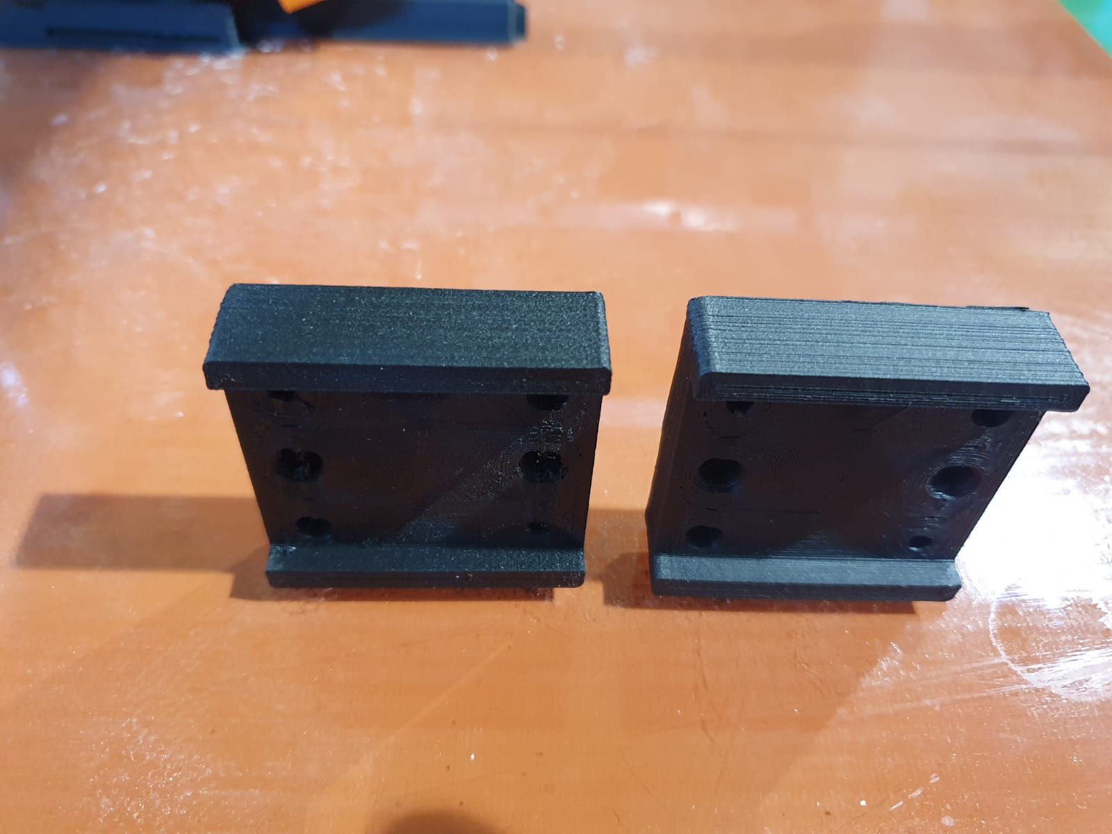
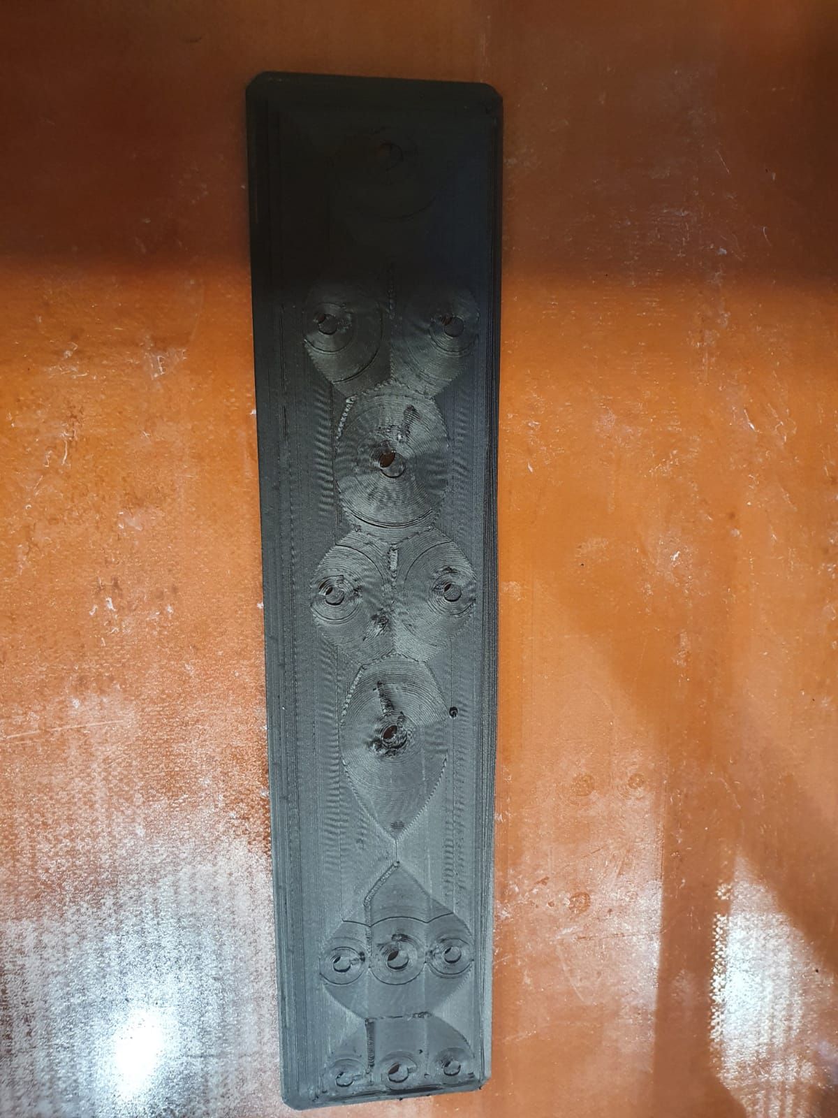
      For the past 3 days I started printing parts with the 3d printer, and for "first prints" stage , the results looked pretty good. Bellow you have photos of the parts that are been printed successfullyPHOTO-2020-10-18-14-57-46.jpg 
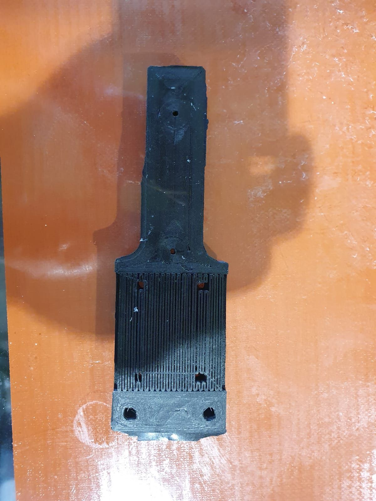
[0_1603268634442_PHOTO-2020-10-18-14-57-46_2jpg](Uploading 100
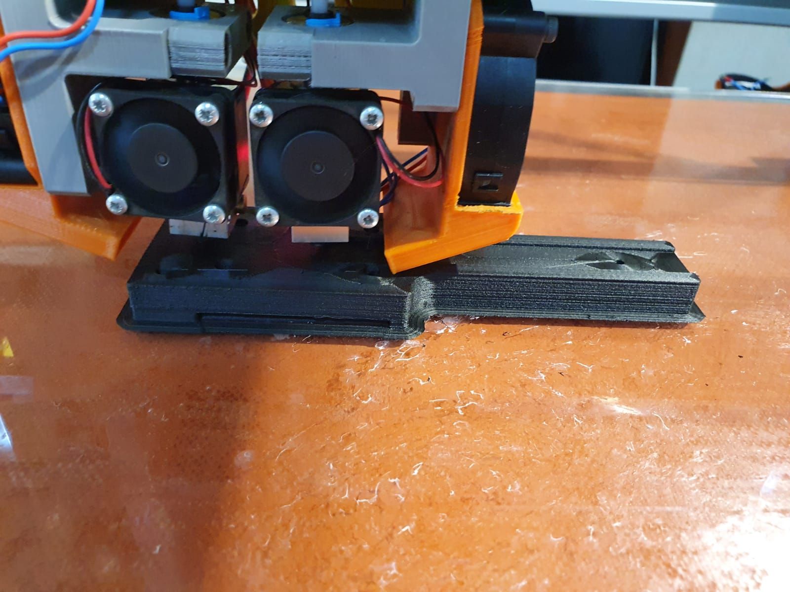
PHOTO-2020-10-18-14-57-47.jpg %) PHOTO-2020-10-18-14-57-47_4.jpg
      Bellow you have a picture of the failed part:
      PHOTO-2020-10-20-21-49-51_2.jpg PHOTO-2020-10-20-21-49-51_1.jpg PHOTO-2020-10-20-21-49-51.jpg PHOTO-2020-10-20-21-49-51_3.jpg
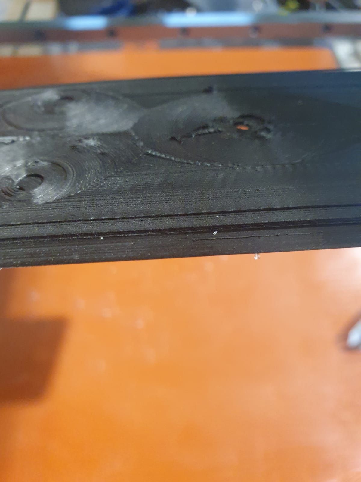
      The last layer is missplaced by 2.6 mm in both x and y directions ; this happenedat an overall height of the failed part of 1.6 mm ; the layer height was set to 0.2 mm

      1 Reply Last reply Reply Quote 0
      • Veti
        Veti last edited by

        thats a layer shift.

        if you have been printing with your printer for a while check the bearings and do some lubrication.

        campeancalin 1 Reply Last reply Reply Quote 0
        • campeancalin
          campeancalin @Veti last edited by

          @Veti that has been take care of

          1 Reply Last reply Reply Quote 0
          • campeancalin
            campeancalin last edited by

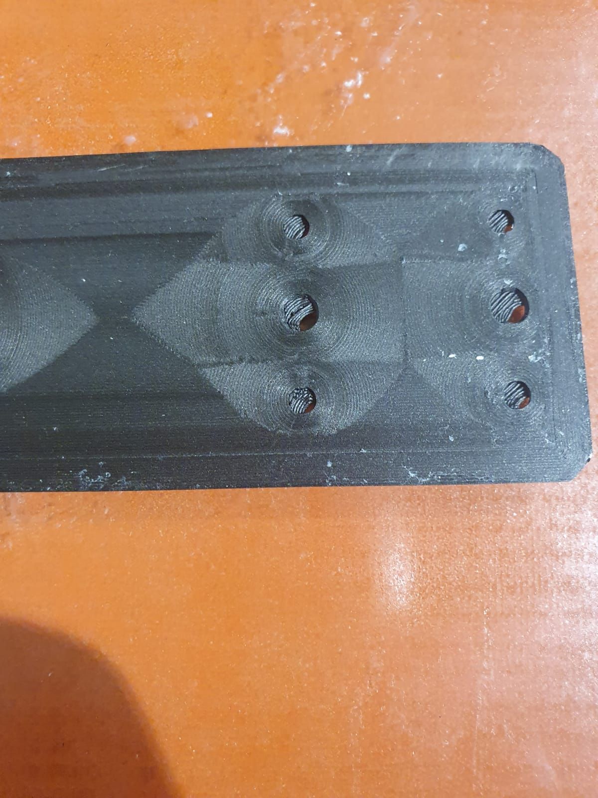
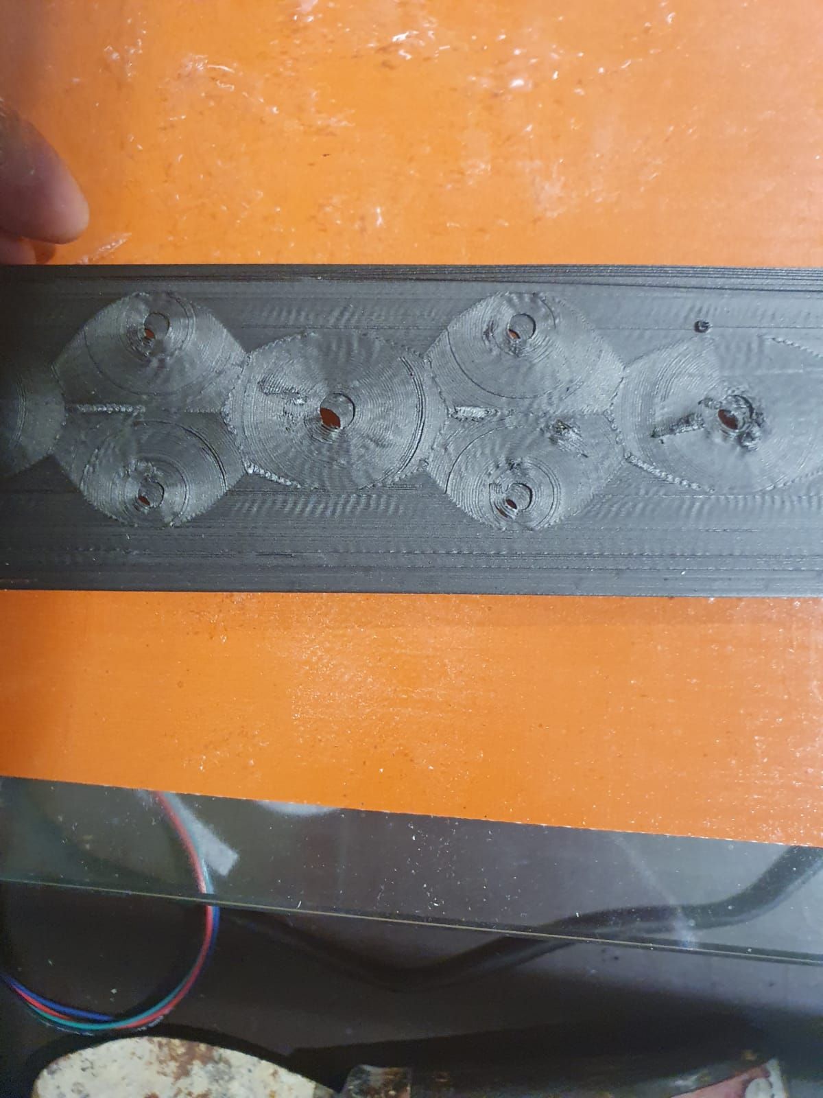
            I started reprinting the part to see when the layer change takes place. I did notice however that at the height of 0.4mm the part started to gain a big blob arount one of the holesIMG_0746H.jpg

            theruttmeister 1 Reply Last reply Reply Quote 0
            • Veti
              Veti last edited by Veti

              the nozzle could easily catch on that and cause the layer shift.

              btw what material is that? because the print quality looks very poor

              campeancalin 1 Reply Last reply Reply Quote 0
              • campeancalin
                campeancalin @Veti last edited by

                @Veti yes, I suspect that too. I am trying however to figure out what can cause that.

                Veti 1 Reply Last reply Reply Quote 0
                • Veti
                  Veti @campeancalin last edited by

                  @campeancalin

                  post your config.g

                  campeancalin 1 Reply Last reply Reply Quote 0
                  • campeancalin
                    campeancalin @Veti last edited by

                    @Veti Bellow you have the config.g file:

                    ; Configuration file for Duet WiFi (firmware version 3)
                    ; executed by the firmware on start-up
                    ;
                    ; generated by RepRapFirmware Configuration Tool v3.1.4 on Mon Oct 05 2020 11:50:08 GMT+0300 (Eastern European Summer Time)

                    ; General preferences
                    G90 ; send absolute coordinates...
                    M83 ; ...but relative extruder moves
                    M550 P"Oscar" ; set printer name
                    M669 K1 ; select CoreXY mode

                    ; Network
                    M551 P"" ; set password
                    M552 S1 ; enable network
                    M586 P0 S1 ; enable HTTP
                    M586 P1 S1 ; enable FTP
                    M586 P2 S0 ; disable Telnet

                    ; Drives
                    M584 X1 Y0 Z2 E3:4 ; set drive mapping; INIT:X=0; Y=1; Z2;E3:4
                    M569 P0 S0 ; physical drive 0 goes backwards
                    M569 P1 S0 ; physical drive 1 goes backwards
                    M569 P2 S1 ; physical drive 2 goes FORWARDS
                    M569 P3 S1 ; physical drive 3 goes FORWARDS
                    M569 P4 S0 ; physical drive 4 goes backwards

                    M350 X16 Y16 Z16:16 E16:16 I1 ; configure microstepping with interpolation ; INIT- M350 X16 Y16 Z16 E16:16 I1
                    M92 X160.00 Y160.00 Z3200.00 E843.26:830.8 ; set steps per mm
                    M566 X600.00 Y600.00 Z12.00 E120.00:120.00 ; set maximum instantaneous speed changes (mm/min)set x and y to 600 from 900
                    M203 X6000.00 Y6000.00 Z360.00 E1200.00:1200.00 ; set maximum speeds (mm/min)
                    M201 X250.00 Y250.00 Z20.00 E250.00:250.00 ; set accelerations (mm/s^2)x and y 250 from 500
                    M906 X1100 Y1100 Z1200 E1200:1200 I80 ; set motor currents (mA) and motor idle factor in per cent changed X1200 Y1200 to X1100 Y1100
                    M84 S30 ; Set idle timeout
                    ; Pressure advance
                    M572 D0:1 S0.05:0.05 ; enabled Pressure advance for both extruders

                    ; Axis Limits
                    M208 X0 Y0 Z0 S1 ; set axis minima
                    M208 X600 Y600 Z525 S0 ; set axis maxima

                    ; Endstops
                    M574 X1 S1 P"!xstop" ; configure active-high endstop for low end on X via pin xstop -added "! to xstop"
                    M574 Y1 S1 P"!ystop" ; configure active-high endstop for low end on Y via pin ystop - added"! to xstop"
                    M574 Z1 S2 ; configure Z-probe endstop for low end on Z

                    ; Z-Probe
                    M950 S0 C"duex.pwm5" ; create servo pin 0 for BLTouch
                    M558 P9 C"^zprobe.in" H5 F120 T6000 ; set Z probe type to bltouch and the dive height + speeds
                    G31 P25 X20 Y37 Z2.32 ; set Z probe trigger value, offset and trigger height- changed from 3.5 to 2.19 to -0.797,to 2.23to 2.316
                    M557 X40:520 Y80:520 P20 ; define mesh grid changed S20 to P3 to P20

                    ; Heaters
                    M308 S0 P"bedtemp" Y"thermistor" T100000 B4138 ; configure sensor 0 as thermistor on pin bedtemp
                    M950 H0 C"bedheat" T0 ; create bed heater output on bedheat and map it to sensor 0
                    M307 H0 B0 S1.00 ; disable bang-bang mode for the bed heater and set PWM limit
                    M140 H0 ; map heated bed to heater 0
                    M143 H0 S250 ; set temperature limit for heater 0 to 120C
                    M308 S1 P"e0temp" Y"thermistor" T100000 B4138 ; configure sensor 1 as thermistor on pin e0temp
                    M950 H1 C"e0heat" T1 ; create nozzle heater output on e0heat and map it to sensor 1
                    M307 H1 B0 S1.00 ; disable bang-bang mode for heater and set PWM limit
                    M308 S2 P"e1temp" Y"thermistor" T100000 B4138 ; configure sensor 2 as thermistor on pin e1temp
                    M950 H2 C"e1heat" T2 ; create nozzle heater output on e1heat and map it to sensor 2
                    M307 H2 B0 S1.00 ; disable bang-bang mode for heater and set PWM limit

                    ; Fans
                    M950 F0 C"fan0" Q500 ; create fan 0 on pin fan0 and set its frequency
                    M106 P0 S1 H-1 ; set fan 0 value. Thermostatic control is turned off
                    M950 F1 C"fan1" Q500 ; create fan 1 on pin fan1 and set its frequency
                    M106 P1 S1 H-1 ; set fan 1 value. Thermostatic control is turned off

                    ; Tools
                    M563 P0 S"Tool 1" D0 H1 F0 ; define tool 0
                    G10 P0 X0 Y0 Z0 ; set tool 0 axis offsets
                    G10 P0 R0 S0 ; set initial tool 0 active and standby temperatures to 0C
                    M563 P1 S"Tool 2" D1 H2 F1 ; define tool 1
                    G10 P1 X0 Y0 Z0 ; set tool 1 axis offsets
                    G10 P1 R0 S0 ; set initial tool 1 active and standby temperatures to 0C

                    ; Custom settings are not defined
                    M912 P0 S-16.95 ; adjustment of the MCU temp read

                    ; Miscellaneous
                    M575 P1 S1 B57600 ; enable support for PanelDue
                    M911 S10 R11 P"M913 X0 Y0 G91 M83 G1 Z3 E-5 F1000" ; set voltage thresholds and actions to run on power loss
                    M501 ; load saved parameters from non-volatile memory

                    1 Reply Last reply Reply Quote 0
                    • Veti
                      Veti last edited by

                      @campeancalin said in 3D printin issues on a core XY equiped with a duet wifi:

                      M308 S0 P"bedtemp" Y"thermistor" T100000 B4138 ; configure sensor 0 as thermistor on pin
                      M308 S1 P"e0temp" Y"thermistor" T100000 B4138 ; configure sensor 1 as thermistor on pin e0temp
                      M308 S2 P"e1temp" Y"thermistor" T100000 B4138 ; configure sensor 2 as thermistor on pin e1temp

                      your thermistor setting is wrong. look up the correct beta value in your thermistor documentation.
                      because of it you are printing at the wrong temperature.

                      what material is that you are printing?

                      campeancalin 1 Reply Last reply Reply Quote 0
                      • campeancalin
                        campeancalin @Veti last edited by

                        @Veti ColorFab XTCF20

                        1 Reply Last reply Reply Quote 0
                        • campeancalin
                          campeancalin last edited by

                          the printheads are 24V E3D V6

                          Veti 1 Reply Last reply Reply Quote 0
                          • campeancalin
                            campeancalin last edited by

                            after changing the B values do I have to redo the PID tunning?

                            1 Reply Last reply Reply Quote 0
                            • Veti
                              Veti @campeancalin last edited by Veti

                              @campeancalin said in 3D printin issues on a core XY equiped with a duet wifi:

                              the printheads are 24V E3D V6

                              if they are genuine e3d then you need 2 values
                              B4725 C7.06e-8

                              This will account for about 20 degrees difference at 200C

                              i would do a pid tune, but the pid value should not change by much.

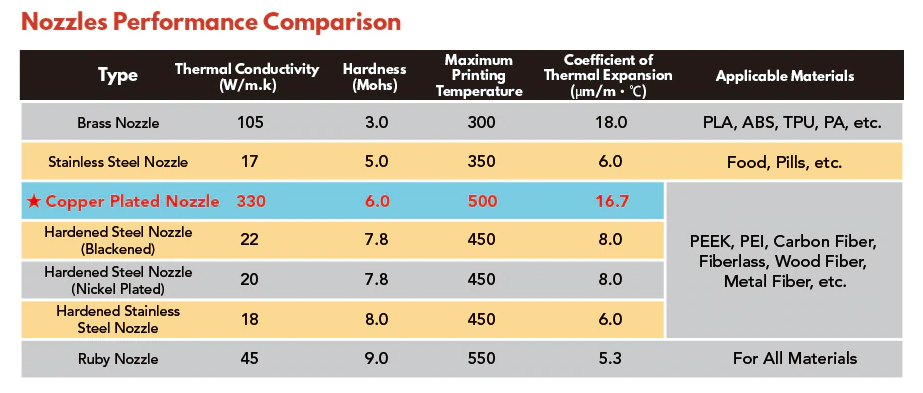
                              btw what nozzle are you using? the carbon filament will destroy a normal brass nozzle and could also account for the blobs you are seeing

                              campeancalin 1 Reply Last reply Reply Quote 0
                              • campeancalin
                                campeancalin @Veti last edited by

                                @Veti It's not a brass nozzle ; reinfoced steel. I plan on having a look at it after it's gone thru a spool of filament.

                                Veti 1 Reply Last reply Reply Quote 0
                                • Veti
                                  Veti @campeancalin last edited by

                                  @campeancalin said in 3D printin issues on a core XY equiped with a duet wifi:

                                  reinfoced steel.

                                  that is ok for wear, but very bad for temperature transfer.

                                  f1aef3d2-a169-4801-aa02-f8ceaa604b0f-image.png

                                  i would suggest that you print a temperature tower.

                                  1 Reply Last reply Reply Quote 0
                                  • campeancalin
                                    campeancalin last edited by

                                    I have a little problem with the PID tunning. Once I've changed the values , it gives me the following error message:

                                    M307 H1 S285
                                    

                                    Error: M307: bad model parameters

                                    1 Reply Last reply Reply Quote 0
                                    • campeancalin
                                      campeancalin last edited by

                                      ; Heaters
                                      M308 S0 P"bedtemp" Y"thermistor" T100000 B4138 ; configure sensor 0 as thermistor on pin bedtemp
                                      M950 H0 C"bedheat" T0 ; create bed heater output on bedheat and map it to sensor 0
                                      M307 H0 B0 S1.00 ; disable bang-bang mode for the bed heater and set PWM limit
                                      M140 H0 ; map heated bed to heater 0
                                      M143 H0 S250 ; set temperature limit for heater 0 to 120C
                                      M308 S1 P"e0temp" Y"thermistor" T100000 B4725 C7.06e-8 ; configure sensor 1 as thermistor on pin e0temp
                                      M950 H1 C"e0heat" T1 ; create nozzle heater output on e0heat and map it to sensor 1
                                      M307 H1 B0 S1.00 ; disable bang-bang mode for heater and set PWM limit
                                      M308 S2 P"e1temp" Y"thermistor" T100000 B4725 C7.06e-8 ; configure sensor 2 as thermistor on pin e1temp
                                      M950 H2 C"e1heat" T2 ; create nozzle heater output on e1heat and map it to sensor 2
                                      M307 H2 B0 S1.00 ; disable bang-bang mode for heater and set PWM limit

                                      jay_s_uk Veti 2 Replies Last reply Reply Quote 0
                                      • jay_s_uk
                                        jay_s_uk @campeancalin last edited by

                                        @campeancalin M303 is used to PID tune, not M307

                                        Owns various duet boards and is the main wiki maintainer for the Teamgloomy LPC/STM32 port of RRF. Assume I'm running whatever the latest beta/stable build is

                                        campeancalin 1 Reply Last reply Reply Quote 0
                                        • campeancalin
                                          campeancalin @jay_s_uk last edited by

                                          @jay_s_uk Thank you

                                          1 Reply Last reply Reply Quote 0
                                          • Veti
                                            Veti @campeancalin last edited by

                                            @campeancalin said in 3D printin issues on a core XY equiped with a duet wifi:

                                            M143 H0 S250 ; set temperature limit for heater 0 to 120C

                                            can you bed really reach 250C? the bed does not look like the special e3d high temperature bed. and those can reach 250, but should not be operated above 200C

                                            campeancalin 1 Reply Last reply Reply Quote 0
                                            • campeancalin
                                              campeancalin @Veti last edited by

                                              @Veti No. I've PID tunned it for a max temp of 100 C

                                              Stephen6309 1 Reply Last reply Reply Quote 0
                                              • Stephen6309
                                                Stephen6309 @campeancalin last edited by

                                                @campeancalin PID doesn't set a max temperature, the M143 does.

                                                1 Reply Last reply Reply Quote 1
                                                • theruttmeister
                                                  theruttmeister @campeancalin last edited by

                                                  @campeancalin
                                                  Looking at the pictures, either you are over-extruding or your first layer is too low (which means you are trying to fit too much material in too little space). That causes material to push up higher than it should, and if the nozzle runs into those lumps it tends to cause layer shifts.

                                                  And if you don't have one already, get a filament drier, CF filled filaments absorb moisture like crazy and need to be dried. If you look closely you might be able to see the filament bubbling as it comes out of the nozzle. Drying the filament for at least 24 hours will make a huge difference to both print quality and material strength.

                                                  Isolate, substitute, verify.

                                                  1 Reply Last reply Reply Quote 1
                                                  • Phaedrux
                                                    Phaedrux Moderator last edited by

                                                    How many walls are you using? Are you using concentric infill?

                                                    It's typical to use only a few walls and solid or rectilinear infill for the rest. Using too many walls can lead to over extrusion building up.

                                                    Z-Bot CoreXY Build | Thingiverse Profile

                                                    1 Reply Last reply Reply Quote 1
                                                    • First post
                                                      Last post
                                                    Unless otherwise noted, all forum content is licensed under CC-BY-SA