Analog joystick setup & possible error in wiring schematic
-
Following the work done by @deckingman in setting up a joystick to jog the carriage around, I decided to try a similar setup except using a common Arduino joystick with analog control and a push button.
I set the button up to run a trigger and then used the analog values to increase speed/distance of each step according to the joystick position.
At this point it's a touch jerky, but essentially works.
It will only run if there is no print loaded and the button is depressed.
I have also set it to not run if the analog value is between -5 & 5 as the potentiometer(s) are not exactly centered, so they don't read zero at rest. This can probably be trimmed.In the process I had a bit of trouble getting both axis working, which I think may be due to an error in the wiring schematic for the Duet 2 wifi, however that part may require verification.
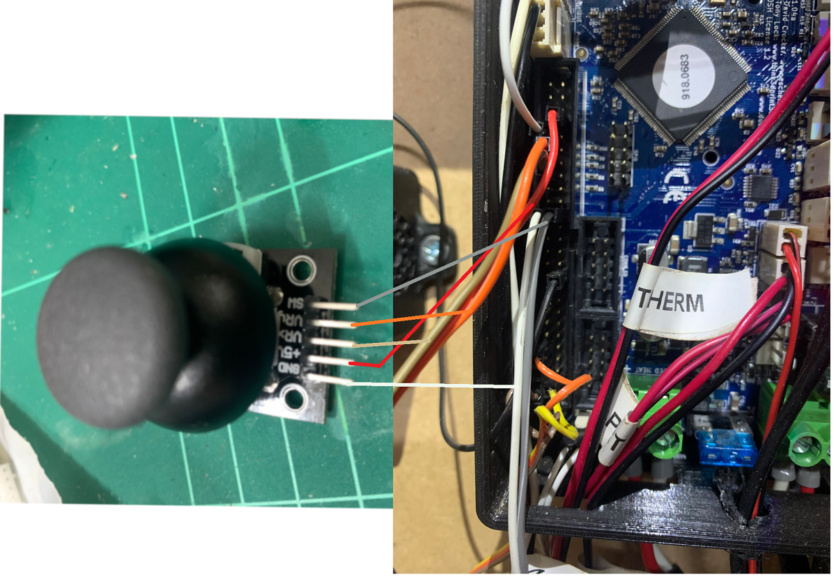
This is my wiring
this is the relevant section of config.g
; Joystick
M308 S3 P"e3temp" Y"linear-analog" A"JoyStick-X" F1 B100 C-100 ; set analog input on E3 Temp with min/max of -100 to 100
M308 S4 P"e5temp" Y"linear-analog" A"JoyStick-Y" F1 B100 C-100 ; set analog input on E5 Temp with min/max of -100 to 100
M581 T7 P7 ; set up trigger for GpIn 7
M950 J7 C"!^exp.29" 	; Input 7 uses Expansion 29 pin activate pullup and inverted
This is the trigger file (trigger7.g)
if job.file.fileName!=null
	echo "Print loaded... Cannot jog carriage"
	M99 ; cancel macro
while sensors.gpIn[7].value=1
	if sensors.analog[3].lastReading < -5 ; lower X
		if sensors.analog[3].lastReading < -5 && sensors.analog[4].lastReading < -5 ; lower X & Y
			G1 X{move.axes[0].machinePosition-abs(sensors.analog[3].lastReading*0.05)} Y{move.axes[1].machinePosition-abs(sensors.analog[4].lastReading*0.05)} F{abs(sensors.analog[3].lastReading*20)} ;
    	else
			G1 X{move.axes[0].machinePosition-abs(sensors.analog[3].lastReading*0.05)} F{abs(sensors.analog[3].lastReading*20)} ;
		;M400
	if sensors.analog[4].lastReading < -5 ; lower Y
		if sensors.analog[3].lastReading < -5 && sensors.analog[4].lastReading < -5 ; lower X & Y
			G1 X{move.axes[0].machinePosition-abs(sensors.analog[3].lastReading*0.05)} Y{move.axes[1].machinePosition-abs(sensors.analog[4].lastReading*0.05)} F{abs(sensors.analog[3].lastReading*20)} ;
		else
			G1 Y{move.axes[1].machinePosition-abs(sensors.analog[4].lastReading*0.05)} F{abs(sensors.analog[4].lastReading*20)} ;
		;M400
	if sensors.analog[3].lastReading > 5 ; higher X
		if sensors.analog[3].lastReading > 5 && sensors.analog[4].lastReading > 5 ; higher X & Y
			G1 X{move.axes[0].machinePosition+(sensors.analog[3].lastReading*0.05)} Y{move.axes[1].machinePosition+(sensors.analog[4].lastReading*0.05)} F{abs(sensors.analog[3].lastReading*20)} ;
		else
			G1 X{move.axes[0].machinePosition+(sensors.analog[3].lastReading*0.05)} F{abs(sensors.analog[3].lastReading*20)} ;
		;M400
	if sensors.analog[4].lastReading > 5 ; higher Y
		if sensors.analog[3].lastReading > 5 && sensors.analog[4].lastReading > 5 ; higher X & Y
			G1 X{move.axes[0].machinePosition+(sensors.analog[3].lastReading*0.05)} Y{move.axes[1].machinePosition+(sensors.analog[4].lastReading*0.05)} F{abs(sensors.analog[3].lastReading*20)} ;
		else
			G1 Y{move.axes[1].machinePosition+(sensors.analog[4].lastReading*0.05)} F{abs(sensors.analog[4].lastReading*20)} ;
	M400
Finally this is the wiring schematic.
The thing is that according to this, thermistor pins 3 & 5 should be on the same row as the 3.3v output pin (43)
However the code only works if I wire to the pins shown, which "should be" Thermistor 4 & 6 (e4temp & e6temp)Or am I looking at the wrong schematic?

M122
M122 === Diagnostics === RepRapFirmware for Duet 2 WiFi/Ethernet version 3.2-beta3.2 running on Duet WiFi 1.02 or later Board ID: 08DGM-917NK-F2MS4-7J1DA-3S86T-TZTWD Used output buffers: 3 of 24 (18 max) === RTOS === Static ram: 24108 Dynamic ram: 100948 of which 44 recycled Never used RAM 4948, free system stack 180 words Tasks: NETWORK(ready,189) HEAT(blocked,308) MAIN(running,445) IDLE(ready,20) Owned mutexes: WiFi(NETWORK) === Platform === Last reset 00:30:17 ago, cause: software Last software reset at 2020-11-16 21:00, reason: User, GCodes spinning, available RAM 4948, slot 2 Software reset code 0x0003 HFSR 0x00000000 CFSR 0x00000000 ICSR 0x0041f000 BFAR 0xe000ed38 SP 0xffffffff Task MAIN Error status: 0x00 MCU temperature: min 35.0, current 35.4, max 36.2 Supply voltage: min 24.2, current 24.3, max 24.5, under voltage events: 0, over voltage events: 0, power good: yes Driver 0: position 0, standstill, SG min/max not available Driver 1: position 0, standstill, SG min/max not available Driver 2: position 0, standstill, SG min/max not available Driver 3: position 0, standstill, SG min/max not available Driver 4: position 0, standstill, SG min/max not available Driver 5: position 0 Driver 6: position 0 Driver 7: position 0 Driver 8: position 0 Driver 9: position 0 Driver 10: position 0 Driver 11: position 0 Date/time: 2020-11-16 21:30:56 Cache data hit count 3062365785 Slowest loop: 13.02ms; fastest: 0.23ms I2C nak errors 0, send timeouts 0, receive timeouts 0, finishTimeouts 0, resets 0 === Storage === Free file entries: 10 SD card 0 detected, interface speed: 20.0MBytes/sec SD card longest read time 1.5ms, write time 2.3ms, max retries 0 === Move === Hiccups: 0(0), FreeDm: 169, MinFreeDm: 169, MaxWait: 0ms Bed compensation in use: none, comp offset 0.000 === MainDDARing === Scheduled moves 0, completed moves 0, StepErrors 0, LaErrors 0, Underruns [0, 0, 0], CDDA state -1 === AuxDDARing === Scheduled moves 0, completed moves 0, StepErrors 0, LaErrors 0, Underruns [0, 0, 0], CDDA state -1 === Heat === Bed heaters = 0 -1 -1 -1, chamberHeaters = -1 -1 -1 -1 Heater 1 is on, I-accum = 0.0 === GCodes === Segments left: 0 Movement lock held by null HTTP is idle in state(s) 0 Telnet is idle in state(s) 0 File is idle in state(s) 0 USB is idle in state(s) 0 Aux is idle in state(s) 0 Trigger is idle in state(s) 0 Queue is idle in state(s) 0 LCD is idle in state(s) 0 Daemon is idle in state(s) 0 Autopause is idle in state(s) 0 Code queue is empty. === Network === Slowest loop: 40.67ms; fastest: 0.00ms Responder states: HTTP(0) HTTP(0) HTTP(0) HTTP(0) FTP(0) Telnet(0), 0 sessions HTTP sessions: 1 of 8 - WiFi - Network state is active WiFi module is connected to access point Failed messages: pending 0, notready 0, noresp 0 WiFi firmware version 1.23 WiFi MAC address bc:dd:c2:89:a0:bb WiFi Vcc 3.38, reset reason Power up WiFi flash size 4194304, free heap 19824 WiFi IP address 192.168.1.163 WiFi signal strength -53dBm, reconnections 0, sleep mode modem Clock register ffffffff Socket states: 0 0 0 0 0 0 0 0 === Filament sensors === Extruder 0 sensor: ok -
Thermistor 3 is on pin 35 and thermistor 5 is on pin 37:
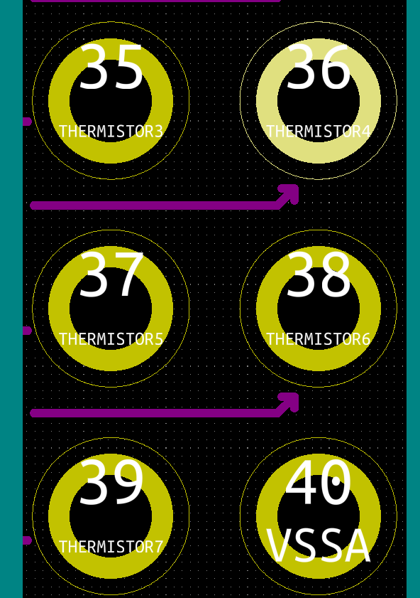
Yes this in on the same row as pin 43 (3.3V)
-
@T3P3Tony said in Analog joystick setup & possible error in wiring schematic:
Thermistor 3 is on pin 35 and thermistor 5 is on pin 37:
Yes this in on the same row as pin 43 (3.3V)
Hi @T3P3Tony
Yet in my pic, you can see that the orange and brown wires from the potentiometers are clearly on the opposite side to pin 43 (3.3v)
Is this...
mis-labeling of the wiring image shown?
Me using an incorrect diagram for model?
Internal allocation of pins?
Incorrect config on my part?Apart from me needing to add some more code to handle all possible combinations of joystick positions a bit better, the code works as shown.
Just a bit concerned about hooking wires up to pins which are not what they "seem" to be.