RRF3.2Beta4.1 Heightmap vs. Spindle/Driver Mapping
-
Good Morning,
I´m trying to understand what's going on and why it is looking like that
")
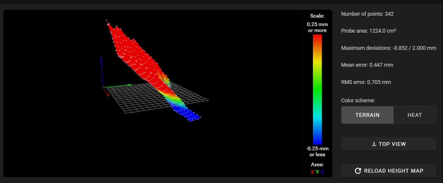
after editing my BLTouch Settings with these additional Parameters and half the Probing Speed quite repeatable Measurements.
M558 P9 H5 F60 T6000 A10 S0.003 B1 (R0.75???)deployprobe.g:
M280 P0 S10is saw there is an additional R Parameter but I can't find any documentation about it.
is there anything to optimize?
My Spindles are at the left Front, rear center, right front about 50mm outside the Bed.
The Bed is a 4mm Aluminium Plate with a PrimaCreator MagneticFlex Steel Plate.This measurement was @ Room Temperature ~21°C
The BLTouch needed about 2-3 attempts to achieve the tolerance specified in the config and go to the next Probing Spot.
my bed.g:
;Probe 3-point
M561                            ; clear any bed transform
G28  				; Home all
G30 P0 X40 Y80 Z-99999          ; Probe near the front left lead-screw
G30 P1 X215 Y395 Z-99999        ; Probe near the rear lead screw
G30 P2 X415 Y80 Z-99999 S3      ; Probe near the front right lead-screw

G30 P0 X40 Y80 Z-99999          ; Probe near the front left lead-screw (Second Pass)
G30 P1 X215 Y395 Z-99999        ; Probe near the rear lead screw (Second Pass)
G30 P2 X415 Y80 Z-99999 S3      ; Probe near the front right lead-screw (Second Pass)

G91                             ; Switch to relative positioning moves
G1 H2 Z5 F1000                  ; Drop the Z-axis (the bed) by 5mm relative to its current position
G90                             ; Revert back to absolute positioning moves
G1 X215 Y210 F6000              ; Position the nozzle at the center of the bed
G30                             ; Probe and set the height as probed
G29 S1 P"heightmap.csv"         ; Load the heightmap
my config.g:
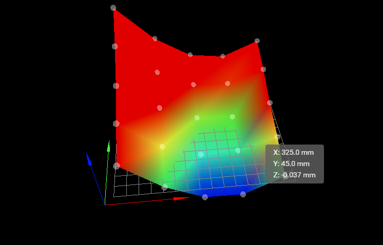
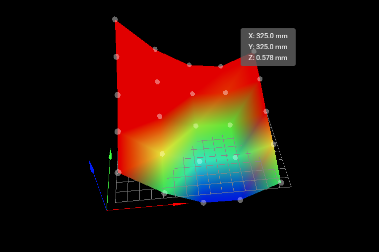
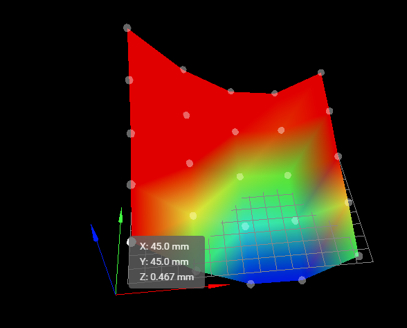
G90                                                          ; Send absolute coordinates...
M550 P"vcore"                                                ; set printer name
M669 K1                                                      ; select CoreXY mode

; Drives
M569 P0.0 S1                                                 ; physical drive 0.0 goes forwards
M569 P0.1 S1                                                 ; physical drive 0.1 goes forwards
M569 P0.2 S0                                                 ; physical drive 0.2 goes forwards
M569 P0.3 S0                                                 ; physical drive 0.5 goes forwards
M569 P0.4 S0                                                 ; physical drive 0.5 goes forwards
M569 P0.5 S0                                                 ; physical drive 0.5 goes forwards
M569 P121.0 S0

M584 X0.0 Y0.1 Z0.2:0.3:0.4 E0.5                     	     ; set drive mapping
M350 E16 I0                                                  ; configure microstepping without interpolation
M350 X16 Y16 Z16 I1                                          ; configure microstepping with interpolation
M92 X159.00 Y159.00 Z806.00 E830.00                          ; set steps per mm

M566 X1500.00 Y1500.00 Z50.00 E120.00                        ; set maximum instantaneous speed changes (mm/min)
M203 X18000.00 Y18000.00 Z1000.00 E750.00                    ; set maximum speeds (mm/min)
M201 X1500.00 Y1500.00 Z75.00 E250.00                        ; set accelerations (mm/s^2)
M906 X1800 Y1800 Z1000 E900 I20                              ; set motor currents (mA) and motor idle factor in per cent
M84 S90                                                      ; Set the idle timeout

;Position of Leadscrews
M671 X0:215:450 Y80:450:80 S5 				     ; Position of Leadscrews

;Define Mesh Grid
M557 X40:395 Y40:395 S100                                    ; define mesh grid

; Endstops
M574 X1 S1 P"121.io2.in"                                     ; configure active-high endstop for low end on X via pin 121.io2.in
M574 Y1 S1 P"io0.in"                                         ; configure active-high endstop for low end on Y via pin io1.in
M574 Z1 S2                                                   ; configure Z-probe endstop for high end on Z

; Z-Probe
M950 S0 C"121.io0.out"                                       ; create servo pin 0 for BLTouch
M558 P9  C"121.io0.in" H4 F60 T6000 A10 S0.005 B1            ; set Z probe type to bltouch and the dive height + speeds
G31 P1000 X0 Y0 Z0.81                                        ; set Z probe trigger value, offset and trigger height

; Axis Limits
M208 X0 Y0 Z0 S1                                             ; set axis minima
M208 X415 Y395 Z400 S0                                       ; set axis maxima

;Duet Laser Filament Monitor
M591 D0 P5 C"io3.in" R30:130 E3.0 S0 			     ; Tolerance 30 to 130%, 3mm comparison length, diabled

; Pressure Advance Tuning
M572 D0 S0.05					             ; Extruder pressure advance

; Cancel Ringing at the defined Freuquenzy
;M593 F40.5						     ; Ringing Frequency

; Heaters
M308 S0 P"temp0" Y"thermistor" T100000 B4138                 ; configure sensor 0 as thermistor on pin temp0
M950 H0 C"out0" T0                                           ; create bed heater output on out0 and map it to sensor 0
M307 H0 B0 S1.00                                             ; disable bang-bang mode for the bed heater and set PWM limit
M140 H0                                                      ; map heated bed to heater 0
M143 H0 S150                                                 ; set temperature limit for heater 0 to 200C
M308 S1 P"121.temp0" Y"thermistor" T500000 B4723 C1.19622e-7 ; configure sensor 1 as thermistor on pin 121.temp0
M950 H1 C"121.out0" T1                                       ; create nozzle heater output on 121.out0 and map it to sensor 1
M307 H1 B0 S1.00                                             ; disable bang-bang mode for heater  and set PWM limit
M143 H1 S500                                                 ; set temperature limit for heater 1 to 500C
M308 S2 P"temp1" Y"thermistor" T100000 B4725 C7.06e-8        ; configure sensor 2 as thermistor on pin temp1
M950 H2 C"out1" T2                                           ; create chamber heater output on out1 and map it to sensor 2
M307 H2 B0 S1.00                                             ; disable bang-bang mode for the chamber heater and set PWM limit
M141 H2                                                      ; map chamber to heater 2
M143 H2 S120                                                 ; set temperature limit for heater 2 to 120C

; Heater Model Parameters
M307 H0 R0.641 C945.3 D3.18 S1.00 V24.1	                     ; PID Parameters Heated Bed
M307 H1 R2.770 C158.7 D5.63 S1.00 V24.0			     ; PID Parameter Mosquito Magnum
M307 H2 A202.7 C76.2 D3.1 S1.0 V24.0 B0			     ; PID Parameters Build Chamber

; Fans
M950 F0 C"121.out2" Q500                                     ; create fan 0 on pin 121.out2 and set its frequency
M106 P0 S0 H-1                                               ; set fan 0 value. Thermostatic control is turned off
M950 F1 C"121.out1" Q500                                     ; create fan 1 on pin 121.out1 and set its frequency
M106 P1 S0 H-1                                               ; set fan 1 value. Thermostatic control is turned off

; Tools
M563 P0 S"mosquito magnum" D0 H1 F0:1                        ; define tool 0
G10 P0 X0 Y0 Z0                                              ; set tool 0 axis offsets
T0                                                           ; select first tool

; Custom settings are not defined
M912 P0 S-14.8						     ; MCU Temperature Calibration
M308 S3 P"drivers" Y"drivers" A"TMC" 			     ; Create sensor for drivers
heightmap.csv
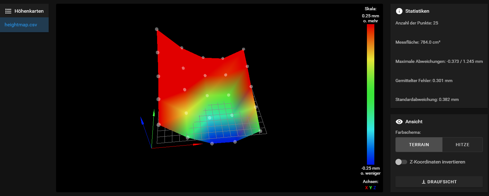
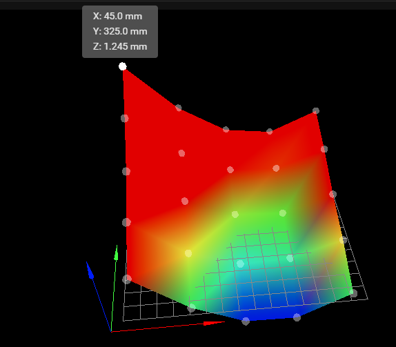
RepRapFirmware height map file v2 generated at 2020-12-22 02:28
xmin,xmax,ymin,ymax,radius,xspacing,yspacing,xnum,ynum
45.00,390.00,45.00,390.00,-1.00,70.00,70.00,5,5
  0.467, -0.045, -0.356, -0.373, -0.037
  0.619,  0.124, -0.105, -0.077,  0.139
  0.765,  0.325,  0.077,  0.042,  0.269
  0.991,  0.517,  0.245,  0.222,  0.445
  1.245,  0.723,  0.398,  0.331,  0.578
PrintHead:
The BlTouch is around 20mm right of the nozzle and 4mm in front
and is at x0 and y5 when homed at x0 y0
Wiring of the Z-Motors:left front Spindle - driver 0.2 rear center - driver 0.3 right front - driver 0.4Duet3 Mainboard
Toolbard LC1RRF 3.2Beta4.1
DWC 3.2Beta4any Tips that I can improve?
Regards Frederik
-
Please check your M671 command.
As I see, the Position of the Leadscrews does not match the Axis minima and maxima.
You write your Leadscrews are 50mm outside the print bed, then they can't be at X0.M208 X0 Y0 Z0 S1
M671 0:215:450 Y80:450:80 S5 -
@gringo i will change the value as soon as i am home and post the results.
its a bit unclear whats the right settings:
from the duet gcode dozuki:
M671: Define positions of Z leadscrews or bed levelling screws
ParametersXnn:nn:nn... List of between 2 and 4 X coordinates of the leadscrews that drive the Z axis or the bed levelling screws
Ynn:nn:nn... List of between 2 and 4 Y coordinates of the leadscrews that drive the Z axis or the bed levelling screws
Snn Maximum correction to apply to each leadscrew in mm (optional, default 1.0)
Pnnn Pitch of the bed levelling screws (not used when bed levelling using independently-driven leadscrews). Defaults to 0.5mm which is correct for M3 bed levelling screws.
Fnn Fudge factor, default 1.0
Order dependencyM671 must come later in config.g than any M667 or M669 command.
ExampleM671 X-15.0:100.0:215.0 Y220.0:-20.0:220.0 ; Z leadscrews are at (-15,220), (100,-20) and (215,220)
but i cant find anything about the Fudge Factor ?
-
I have configured it like this:
M671 X-132:148:428 Y-25:385:-55 S5 ;Leadscrew Position
M208 X-88: 290 U0: 380 Y-25: 325 Z0: 270 ; Axis minima and maxima -
@Frederik said in RRF3.2Beta4.1 Heightmap vs. Spindle/Driver Mapping:
but i cant find anything about the Fudge Factor ?
It can be used to exaggerate the amount of correction in cases where it doesn't correct enough per pass.
M558 R is a rest period after the probing move to allow the probe to settle. For the BLTouch R0.5 or so works well and causes it to rest for half a second before probing again.
M671 defines the position of the lead screws
The order must match the order of the motors defined in M584
In bed.g you probe as close to the lead screws as you can in the same order as the lead screws are defined. -
@Frederik
I have found that slowing down the maximum Z speed can help with tolerance. Try adding a M203 Z100 before any bed probing moves and M203 Z1000 after the bed probing is finished to restore the speed back to your config settings. You may be able to push the speed a little higher Z100.Once you have your setting dialed in correctly you can use a While loop to get a perfect bed level.
while true
	G30 P0 X40 Y80 Z-99999          ; Probe near the front left lead-screw
        G30 P1 X215 Y395 Z-99999        ; Probe near the rear lead screw
        G30 P2 X415 Y80 Z-99999 S3      ; Probe near the front right lead-screw
	M409 K"move.calibration.initial.deviation" F"f"
	if move.calibration.initial.deviation <= 0.001 && move.calibration.initial.deviation >= -0.001
		echo "Passed"
		break
	continue
Please do not try this until you know your setting are correct as this code has no safety checks and will break parts if misconfigured. You can add safety checks if you wish.
Also if your bed temp is not stable it will not pass these tolerances. -
Console output of 3 point Leveling:
G32
Leadscrew adjustments made: 0.810 0.762 0.377, points used 3, (mean, deviation) before (0.623, 0.151) after (-0.000, 0.000)
Leadscrew adjustments made: 0.013 0.161 -0.115, points used 3, (mean, deviation) before (-0.012, 0.105) after (-0.000, 0.000)
Height map loaded from file heightmap.csv
after i edited the standard BLtouch Line to:
´´´
H4 F60 T6000 A10 S0.005 B1 it got from around 0.xx1 values to 0.0xx values at the second round probing with F120 i never saw values like that. if i change the value S0.005 to 0.003 i got an Error Message: unconsistend Z Values.... i also tried to play sith the setscrew on top of the bltouch and generated makro Files for Selftest and Error Reset. after i send these 2 Makkros the sensor is working again without touching the cabling . so i think thats probably a setting /software issue.i try to make some photos for reference
Head at Endstops = X0 Y0
Nozzle Tip is at
-
what a timing, the last Time i posted a question about trigger heigt Problems i ordered a few shottky diodes bat 43 -do35:
Bauform DO-35
Elektrische Werte
URRM 30 V
UF 0,33 V
IF(AV) 0,2 A
IFSM 4 A
IR 0,5 µAI have an unsused inductive Probe here thats working witht 24 V .
could i connect it with that diode savely to an unused IOpin only for testing purposes , if there is a hardware error or other problem on the bltouch ? -
For the BLtouch try this command
M558 P9 H4 F60 T6000 A10 B1 R0.5
Don't specify S at all, let it use the default.
Now if you do a test of G30 S-1 several times in a row, how consistent are the results?
Why do you think there is a problem with the BLTouch?
Error Message: unconsistend Z Values
That will happen if you use too tight a tolerance in S.
-
@Frederik
It looks like the second pass is better then the first.
If your setting are not prefect it may take several more rounds depending on the tolerance you want.This is my output and it starts out much closer then your first attempt. I only have two Z motors instead of three hence only two probe points. As @Phaedrux said I also use the default S value and it works fine.
Leadscrew adjustments made: 0.005 0.005, points used 2, (mean, deviation) before (0.005, 0.000) after (-0.000, 0.000) Leadscrew adjustments made: -0.007 0.016, points used 2, (mean, deviation) before (0.004, 0.004) after (0.000, 0.000) Leadscrew adjustments made: -0.012 0.026, points used 2, (mean, deviation) before (0.006, 0.006) after (-0.000, 0.000) Leadscrew adjustments made: -0.014 0.047, points used 2, (mean, deviation) before (0.015, 0.010) after (0.000, 0.000) Leadscrew adjustments made: -0.080 0.095, points used 2, (mean, deviation) before (0.004, 0.029) after (-0.000, 0.000) Leadscrew adjustments made: -0.098 0.245, points used 2, (mean, deviation) before (0.066, 0.056) after (0.000, 0.000) -
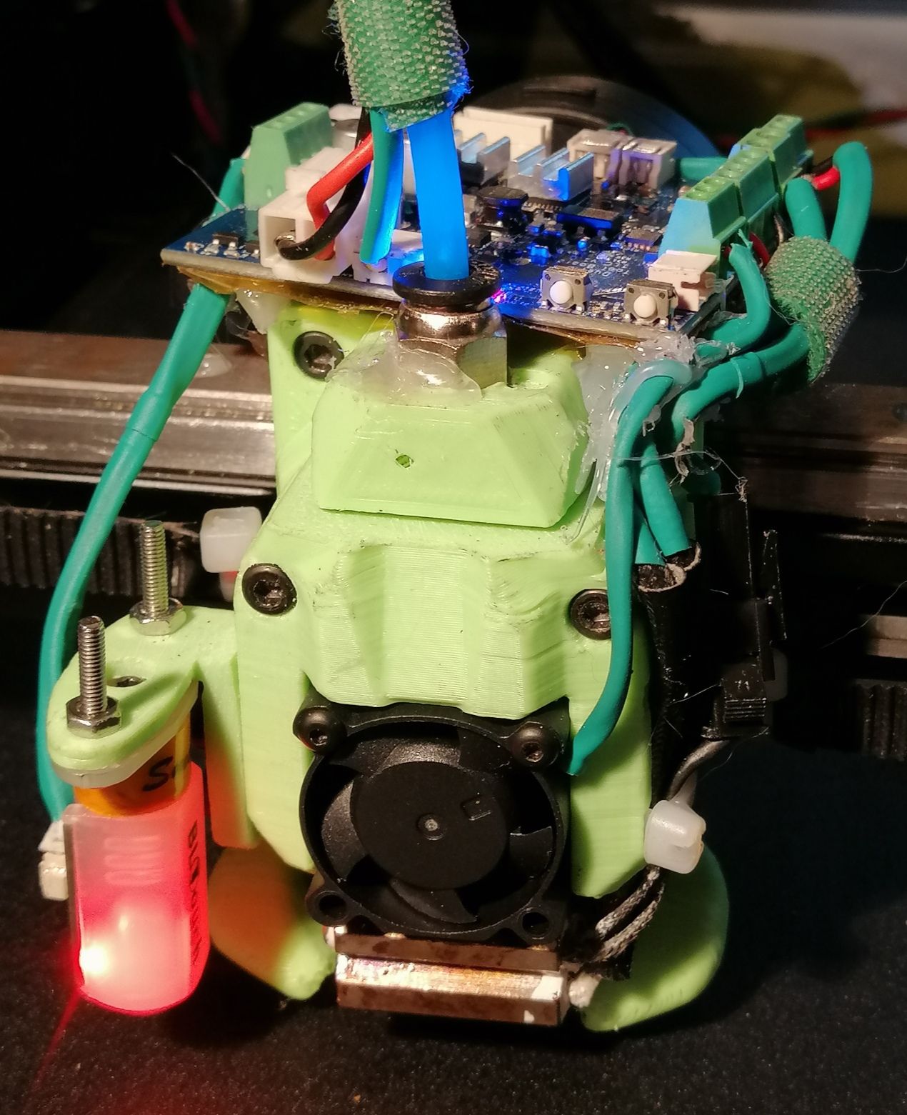
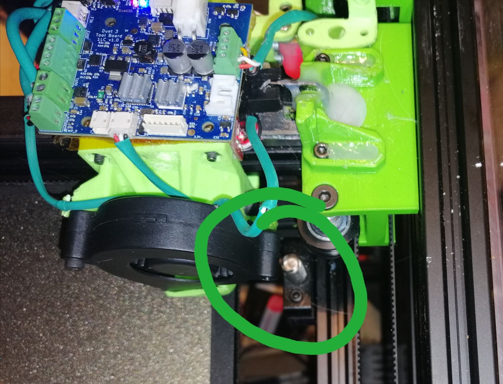
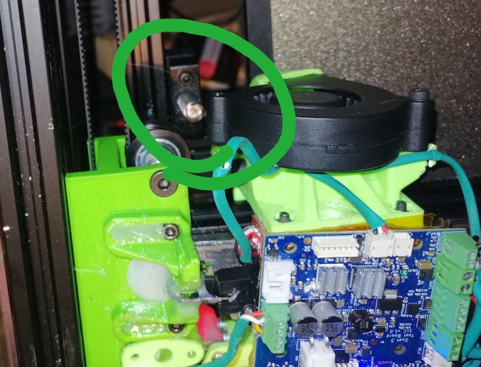
@Phaedrux I was reading on the antclabs web page that the v3. 1 is measuring within 0.005 mm and the results im getting are different every time I generate a Heightmap
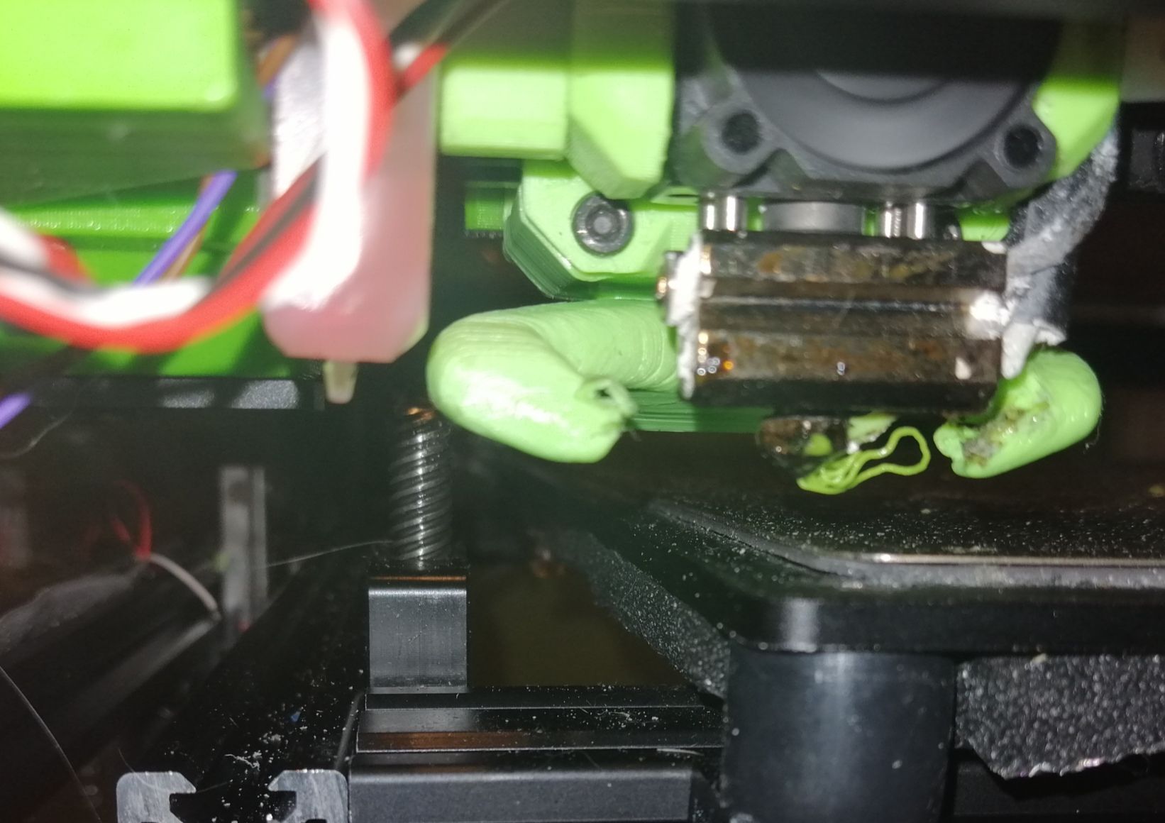
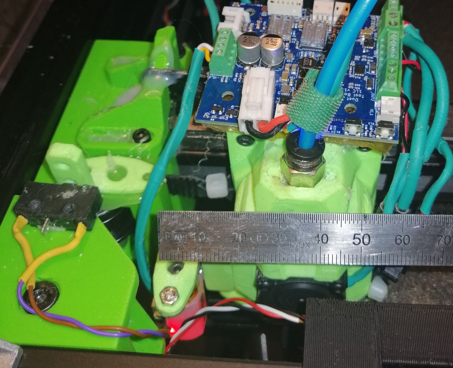
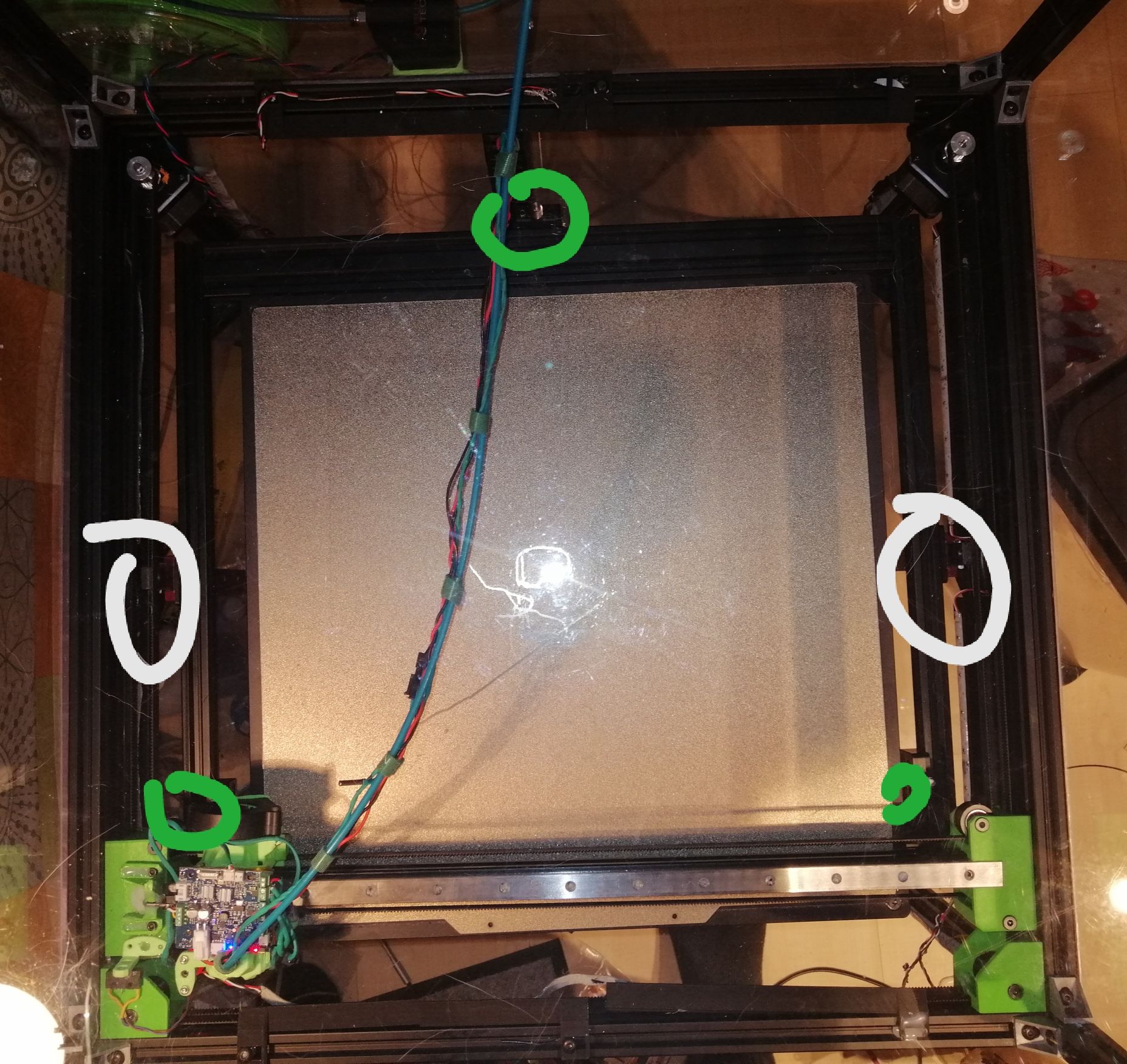
Here are the pictures of my head and in green the position of my spindles and white the position of mgn15 rails to eliminate any z wobble

-
-
@Frederik The different Heightmaps is because your Leadscrew deviation is not 0 before you generate the Heightmap.
-
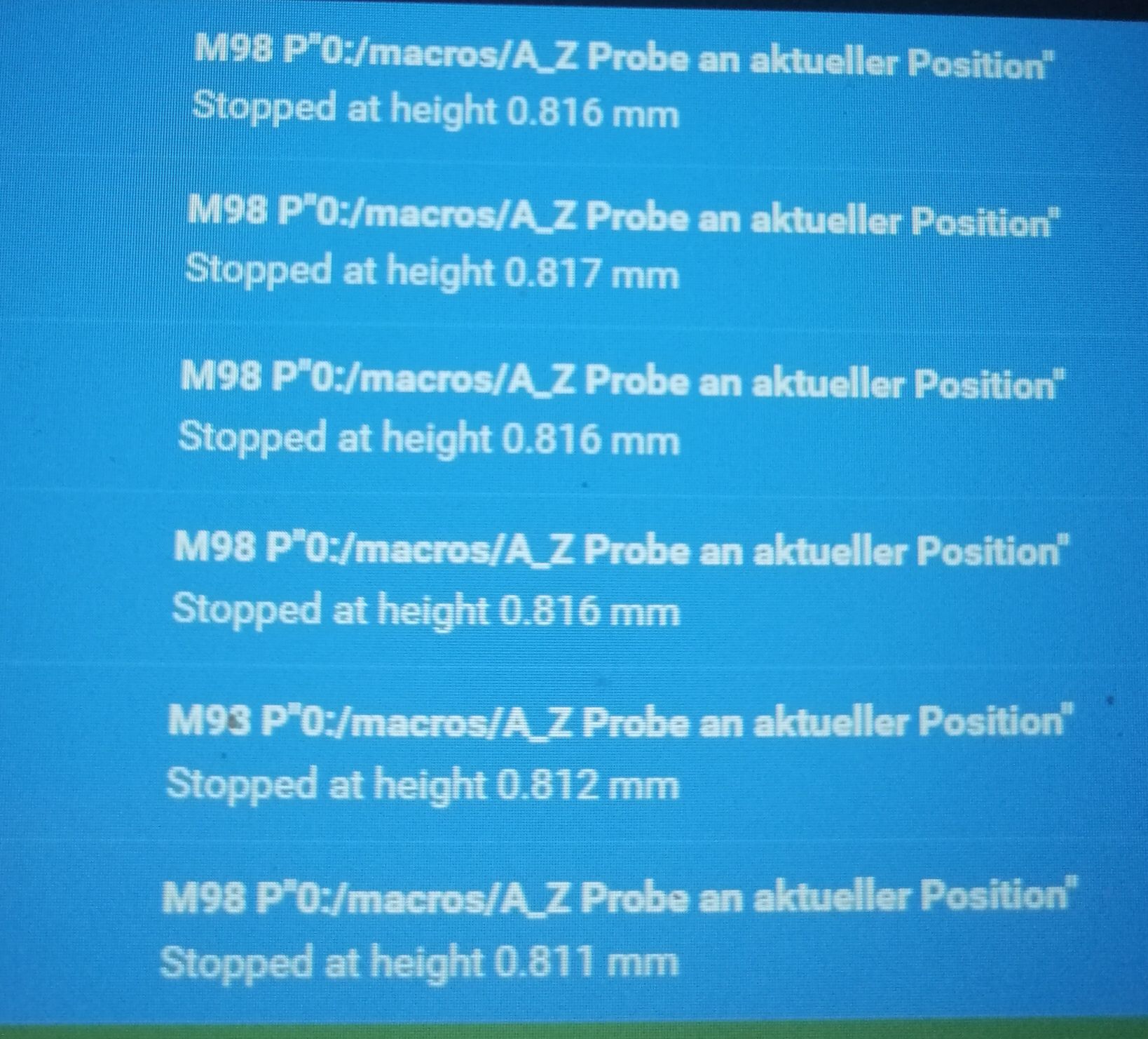
@Phaedrux one moment. I probing single spots and checking the values before and after the z probe code change
-
@3dML I delete the Heightmap and compensation bevor generating a new mesh.
Is that wrong?
And after startup only a g32 - 3 point level +loading of Heightmap.csv (bed.g)
-
@3dML the showed Heightmap was generated at room temperature. To have a baseline when starting test at different standard bed temperatures. Like 60, 90, 100 etc
How Lo g would you give the bed before starting the measurements, so that the temp is as evenly as possible
-
If you run the 3point calibration multiple time it should return a smaller deviation each time hence the reason I use a while loop and an if statement to check the deviation value. It will continue to run until it passes the tolerance set by the if statement.
You could put this code in a macro and run it multiple time to see how small you can get the deviation.
G30 P0 X40 Y80 Z-99999 ; Probe near the front left lead-screw G30 P1 X215 Y395 Z-99999 ; Probe near the rear lead screw G30 P2 X415 Y80 Z-99999 S3 ; Probe near the front right lead-screw -
-
@Frederik said in RRF3.2Beta4.1 Heightmap vs. Spindle/Driver Mapping:
And after startup only a g32 - 3 point level +loading of Heightmap.csv (bed.g)
generate a Heightmap
If you can do a 3point calibration the a deviation of 0 or as close as you can get it you should not have to generate a new Heightmap every time you do a 3point calibration.
The time to temp all depends on your setup.
I have a 750w heater that covers the entire 300mm bed with a temp sensor to control the heat in a slot cutout of the magnet for the flex sheet so very close to the top of the bed. I also have a temp sensor on the heater pad itself so once they both stabilize its good to go. If you are only measuring temp at the heater pad it will take a while for the top of the bed to reach an even temp unless the bed is very thin.
@Frederik said in RRF3.2Beta4.1 Heightmap vs. Spindle/Driver Mapping:
Changed bltouch config to H3 F60 T6000 A10 B1 R0.5
What was the max Z speed for this test? The last 4 readings look good. Too high of a Z speed can cause the shift between the second and third reading.
-
@3dML Z Probing speed F60 normal in the RRF config tool was F120