Duet 5 mini Feedback
-
I am in the process of setting up the mini 5+.
Some feedback so far as its important.
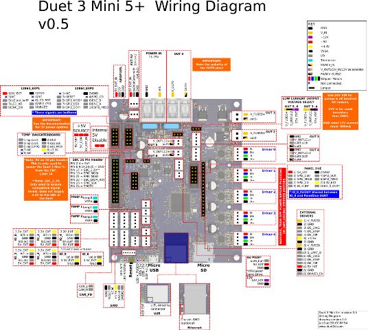
The wiring Diagram for the IO 0-4 Ports is in the wrong order.
https://duet3d.dozuki.com/Wiki/Duet_3_Mini_5plus_WiringIn the configurator i can only select out3-5 for fan.
But the mini 5 has out6 as well.For BLtouch i can select io7.out. But there is no io7.
-
@Veti said in Duet 5 mini Feedback:
I am in the process of setting up the mini 5+.
Some feedback so far as its important.
The wiring Diagram for the IO 0-4 Ports is in the wrong order.
https://duet3d.dozuki.com/Wiki/Duet_3_Mini_5plus_WiringIn the configurator i can only select out3-5 for fan.
But the mini 5 has out6 as well.For BLtouch i can select io7.out. But there is no io7.
technically there are x7 outputs from io0 to io6 so i wouldn't say the wiring diagram is wrong at all, i would say its more a you cant get your head around the way the ports are numbered more than anything else.
-
io7 is a problem in the configurator not the wiring diagram.
-
@Veti said in Duet 5 mini Feedback:
io7 is a problem in the configurator not the wiring diagram.
BUT YOU SAID: The wiring Diagram for the IO 0-4 Ports is in the wrong order.
So YOU need to make your mind up what is wrong one minute you wrote it was the wiring diagram now you are saying its the config tool, do you expect people to be mind readers?
And the ports io0 to io6 are all CORRECT
-
Also I would advise using the config tool only as as method of obtaining a basic layout of the structure and then examining the wiring diagram AND the duet g.code page which will allow you to fully configure the board in the way you want
And generate a good config.g
-
with order i mean the 3.3v is actually the 5v in and out are also swapped.
-
You didnt say that originally so again do you expect people to be mind readers ?
-
sorry if it wasnt clear what i mean in the wrong order
-
@CaLviNx said in Duet 5 mini Feedback:
Also I would advise using the config tool only as as method of obtaining a basic layout of the structure and then examining the wiring diagram AND the duet g.code page which will allow you to fully configure the board in the way you want
And generate a good config.gmy config.g is already set up.
its just a bug that i noticed in the configurator that for bltouch you can select a port that does not exist.
-
I'm told my mini 5 is sitting in "customs" in larnaca so until i actually get my hands on it i cant comment as to whether 3.3 & 5v are swapped or not, i await someone from the duet team to provide an explanation
(EDIT) looking at the diagram between the mini5 and the duet 3 they both show the order for each plug as being:
3.3v
ioX.in
GND
ioX.out
5V EXTSo it would be somewhat strange for them to change things
-
img upload in the forum isnt working for some reason
as you can see the io0 lowest pin close to the 26 pin header is 5v in the diagram its 3.3v
my endstops did not work at first because i wired them according to the diagram.
but the in and out are swapped. -
i wouldnt trust a screen print, now a multi-meter showing me what is actually being output to what pin i would
-
@CaLviNx said in Duet 5 mini Feedback:
i wouldnt trust a screen print, now a multi-meter showing me what is actually being output to what pin i would
i already confirmed it with my endstops.
-
-
the page i linked says Revision 0.4 and 0.5 above the picture
change is 0.5 are here https://duet3d.dozuki.com/Wiki/Duet_3_Mini_5plus_Hardware_overview#Section_Revision_0_Num_5
-
yes but if you print the picture off it only shows as being 0.5
-
-
I confirm, the pinout of IO0 thru IO5 in the wiring diagram is wrong. The pin labels on the underside of the board are correct.
-
Apologies. I have fixed the diagram in the documentation.
Thanks @Veti for reporting the issue.
-
Changes for the duet configurator for duet mini 5.
PWM Control Channel (BLTouch only)
according to https://duet3d.dozuki.com/Wiki/Duet_3_Mini_5plus_Hardware_overview#Section_IO_port_pin_capabilities
it should be io1-io3 out
certainly not io7.out as that does not existz probe input pin
i would assume that it could also be io1-io3. io6 works as well. so maybe io0-6Fan mapping. maybe rename vfd to out6/vfd to specify the 4th fan header.