capacitive sensors PNP (NC) 10-24V for endstops on a Duet Wifi
-
Hi,
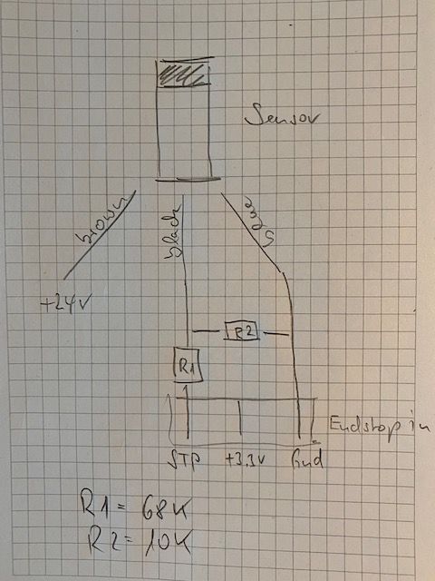
@fcwilt I connected the PNP (NC) sensor brown to 24 V, black with R1 68K to STP and blue to GND. R2 with 10K i connected from GND to black.
Control LED on board is out, LED on Sensor is on. When in end position LED on board is on and LED on sensor out. Seems correct to me.
But in both cases M119 says endstop is not connected.
Config is...
; Endstops
M574 X2 S1 P"^!xstop" ; configure active-high endstop for high end on X via pin !xstop
M574 Y2 S1 P"^!ystop" ; configure active-high endstop for high end on Y via pin !ystop
M574 Z2 S1 P"^!zstop" ; configure active-high endstop for high end on Z via pin !zstopWhat I'm doing wrong?
Frequency of the sensor is 3000Hz, power range 10....30V
Gerd
-
@Gerd said in capacitive sensors PNP (NC) 10-24V for endstops on a Duet Wifi:
But in both cases M119 says endstop is not connected.
please post the actual output
also check that you are actually on firmware version 3.2
post the output of m115 -
@Veti said in capacitive sensors PNP (NC) 10-24V for endstops on a Duet Wifi:
@Gerd said in capacitive sensors PNP (NC) 10-24V for endstops on a Duet Wifi:
But in both cases M119 says endstop is not connected.
please post the actual output
also check that you are actually on firmware version 3.2
post the output of m115m119
Endstops - X: not stopped, Y: not stopped, Z: not stopped, Z probe: not stoppedm115
FIRMWARE_NAME: RepRapFirmware for Duet 2 WiFi/Ethernet FIRMWARE_VERSION: 3.2 ELECTRONICS: Duet WiFi 1.02 or later FIRMWARE_DATE: 2021-01-05 -
hmm if the led on the board changes, it should also change with m119.
maybe the level of the signal is not correct, but i can not comment on that. -
@Veti said in capacitive sensors PNP (NC) 10-24V for endstops on a Duet Wifi:
hmm if the led on the board changes, it should also change with m119.
maybe the level of the signal is not correct, but i can not comment on that.i connected to gnd of the Endstops. Is this correct?
-
you connected the signal to gnd?
the signal should go to the stop pin -
@Veti said in capacitive sensors PNP (NC) 10-24V for endstops on a Duet Wifi:
you connected the signal to gnd?
the signal should go to the stop pinno i connected Signal to stop pin and ground of the sensor to ground pin of the Endstop.
but there is also the ground nearby the Vin which I could use.
-
at moment i only connected 1 of the 3 Endstops. Could this be a problem?
-
I measured at stop (signal) pin 0V when closed and 2.95V when opened.
-
This post is deleted! -
@Gerd said in capacitive sensors PNP (NC) 10-24V for endstops on a Duet Wifi:
I measured at stop (signal) pin 0V when closed and 2.95V when opened.
Those values should be fine.
However your description of how the resistors are connected does not match the documentation you linked to.
Perhaps you description is simply incorrect because the documentation is consistent with my tests.
What board are you using?
What firmware is it running?
Thanks.
Frederick
-
-
@Gerd said in capacitive sensors PNP (NC) 10-24V for endstops on a Duet Wifi:
The diagram is consistent with your description.
It's just different from the suggested circuit in the documentation.
But what matters is the resultant signal levels and they appear to be good if they are measured on the input pin.
Frederick
-
@fcwilt said in capacitive sensors PNP (NC) 10-24V for endstops on a Duet Wifi:
The diagram is consistent with your description.
It's just different from the suggested circuit in the documentation.
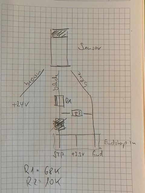
But what matters is the resultant signal levels and they appear to be good if they are measured on the input pin.better?
-
what is about config.g? could there something be wrong?
-
@Gerd said in capacitive sensors PNP (NC) 10-24V for endstops on a Duet Wifi:
@fcwilt said in capacitive sensors PNP (NC) 10-24V for endstops on a Duet Wifi:
The diagram is consistent with your description.
It's just different from the suggested circuit in the documentation.
But what matters is the resultant signal levels and they appear to be good if they are measured on the input pin.better?
Well only you know what you actually wired.
If the new diagram is correct it IS consistent with the documentation AND makes more sense based on my tests.
But, as mentioned, the signal levels are what matter and they seem fine.
Now back to my questions:
What board are you using and what version of firmware is it running?
Thanks.
Frederick
-
@fcwilt said in capacitive sensors PNP (NC) 10-24V for endstops on a Duet Wifi:
@Gerd said in capacitive sensors PNP (NC) 10-24V for endstops on a Duet Wifi:
@fcwilt said in capacitive sensors PNP (NC) 10-24V for endstops on a Duet Wifi:
The diagram is consistent with your description.
It's just different from the suggested circuit in the documentation.
But what matters is the resultant signal levels and they appear to be good if they are measured on the input pin.better?
Well only you know what you actually wired.
If the new diagram is correct it IS consistent with the documentation AND makes more sense based on my tests.
But, as mentioned, the signal levels are what matter and they seem fine.
Now back to my questions:
What board are you using and what version of firmware is it running?
Thanks.
Frederick
duet wifi 1.02 with RRF v3.2
-
@Gerd said in capacitive sensors PNP (NC) 10-24V for endstops on a Duet Wifi:
duet wifi 1.02 with RRF v3.2
Great. Thanks.
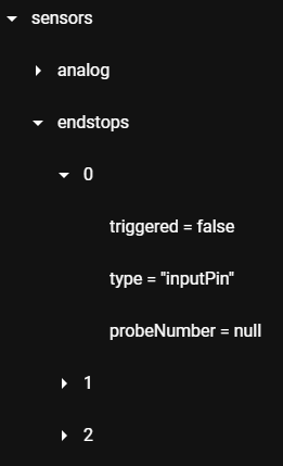
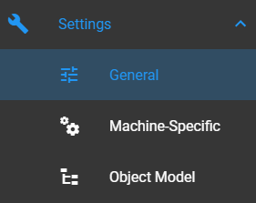
Have you started the Object Model browser plug-in? It would appear as an option in the DWC Settings section.
Frederick
-
@fcwilt said in capacitive sensors PNP (NC) 10-24V for endstops on a Duet Wifi:
@Gerd said in capacitive sensors PNP (NC) 10-24V for endstops on a Duet Wifi:
duet wifi 1.02 with RRF v3.2
Great. Thanks.
Have you started the Object Model browser plug-in? It would appear as an option in the DWC Settings section.
Frederick
not yet
-
@Gerd said in capacitive sensors PNP (NC) 10-24V for endstops on a Duet Wifi:
not yet
You may want to do that as it makes it easy to verify what the firmware is seeing on the inputs.
Frederick