RRF3.3beta1 - Axis skew compensation - InputShapingTypes - PA
-
Hello,
I wanted to play a little bit with the axis skew compensation, PA & the new implemented options fort Input shaping.
- Axis Skew Compensation:
I downloaded and printed the 90mm calibration file.
from https://github.com/reprappro/RepRapFirmware...I found only this example in the dozuki regarding Skew Compensation:
M556 S100 X0.7 Y-0.2 Z0.6Is the S-Parameter 100 correct , even if there are only the 60mm and 90mm calibration files online ?
Then the X -Parameter would be the deviation on the X-labeled end, when i measure the parts as showed in the example picture ?
so the 2 parts would be 99.3mm ??? and X=0.7 ?and so on for the Y and Z values ?
so far so good, but how is that working with the 60mm File ?
M556 Parameters:
Snnn Height of the measured distances
Xnnn Deviation in X direction
Ynnn Deviation in Y direction
Znnn Deviation in Z direction
Pnnn Apply XY compensation to Y axis instead of X (defaults to 0, requires RRF 3.2-b4 or newer)Description
This tells software the tangents of the angles between the axes of the machine obtained by printing then measuring a test part. The S parameter (100 here) is the length of a triangle along each axis in mm. The X, Y and Z figures are the number of millimeters of the short side of the triangle that represents how out of true a pair of axes is. The X figure is the error between X and Y, the Y figure is the error between Y and Z, and the Z figure is the error between X and Z. Positive values indicate that the angle between the axis pair is obtuse, negative acute.
- Input Shaping
M593 F40.5 ; cancel ringing at 40.5Hz was the command that i knew.
But Today , i saw the new Types like:- ZVD
- ZVDD
- DAA
- EI2
whats the difference between them ? what are the benefits ?
Ís it possible to define more than 1 frequenzy?- Pressure Advance
I am running a Mosquito Magnum with an original Bondtech BMG as DirectDrive. My retraction is set at 0.5mm with 40mm/s speed.
When i was testing PA Values on a 100mmx50mmx40mm Box with 1 perimeter , i was surprised that the value that worked the best was between 0.065 and 0.080. At 0.090, holes started to form on the decceleration side.
With Values between 0.005 and 0.045 , the holes where on the acceleration side.Even with no Pressure Advance activated, i get small holes at the start of some spots on sharp coners etc.
The other Problems are all gone since the Firmware Update to 3.3beta1
Regards Frederik
-
I just saw this my self. Wondering what the difference are also. It was not there 4 weeks ago.
-
1: „S“ should be the measured distance. S100 is just an example in the gcode wiki.
2: those are new methods / approaches for input shaping. After you’ve found your correct frequency I would print a medium sized XYZ test cube with each setting (P1, P2, P3, P4) and chose the best looking one. That’s what I did and the result with ZVDD was imo the best but that may be machine dependent. What those types mathematically exactly do I cannot tell though. The papers I found online were quite scientific. Maybe someone else can give a short answer to that.
But I would not use a unstable build to test this!3: It’s a beta version, so bugs can be expected. Holes in the print sound like the same problem I’m having with 3.3b1.
Would you mind resetting your printer, start a print which shows the problem, pause it after the problem happens and enter M115 in the web interface console. I wonder if you also have driver timeouts causing the inconsistencies. -
The only input shaping implemented in 3.3beta1 is DAA. The other settings are there to support ongoing development.
Duet WiFi hardware designer and firmware engineer
Please do not ask me for Duet support via PM or email, use the forum
http://www.escher3d.com, https://miscsolutions.wordpress.com -
That would mean my printer has slightly different pronounced ringing on the print‘s surface (looking at it with a magnifying glass and lightning from above) depending on the placement on the bed as I printed four cubes in sequence with different „P“ setting for M593 from far front to far back. That’s interesting...
-
@Argo said in RRF3.3beta1 - Axis skew compensation - InputShapingTypes - PA:
That would mean my printer has slightly different pronounced ringing on the print‘s surface (looking at it with a magnifying glass and lightning from above) depending on the placement on the bed as I printed four cubes in sequence with different „P“ setting for M593 from far front to far back. That’s interesting...
Can you provide a photo? What is the range of ringing frequencies? The more advanced forms of input shaping current being implemented can suppress ringing over a band of frequencies.
Duet WiFi hardware designer and firmware engineer
Please do not ask me for Duet support via PM or email, use the forum
http://www.escher3d.com, https://miscsolutions.wordpress.com -
I first found my ringing frequency and measured as best as I could. It's set for 46.3hz for all cubes placed from back to front, printed in sequence.
1st M593 disabled:

2nd EI2:

3rd ZVDD:

IMO the 3rd with ZVDD setting looks the best but then it's the placement on the printer and not the feature as it's not implemented yet and just the usual DAA?!
")
-
@dc42 ok thanks for the info. Will the other be also implemented?
Then I will stick to DAA at the moment -
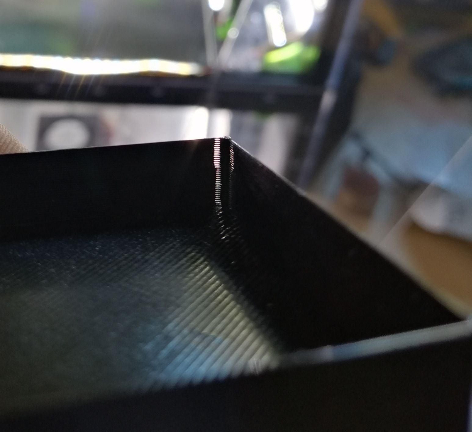
@Argo with holes, I meant this little spots around the corner. With low PA values, they are at the accelerating side, with values at around 0.080 and up, they start to appear at the deccelerating side
-
@Argo Axis Skew compensation
Could you explain that please?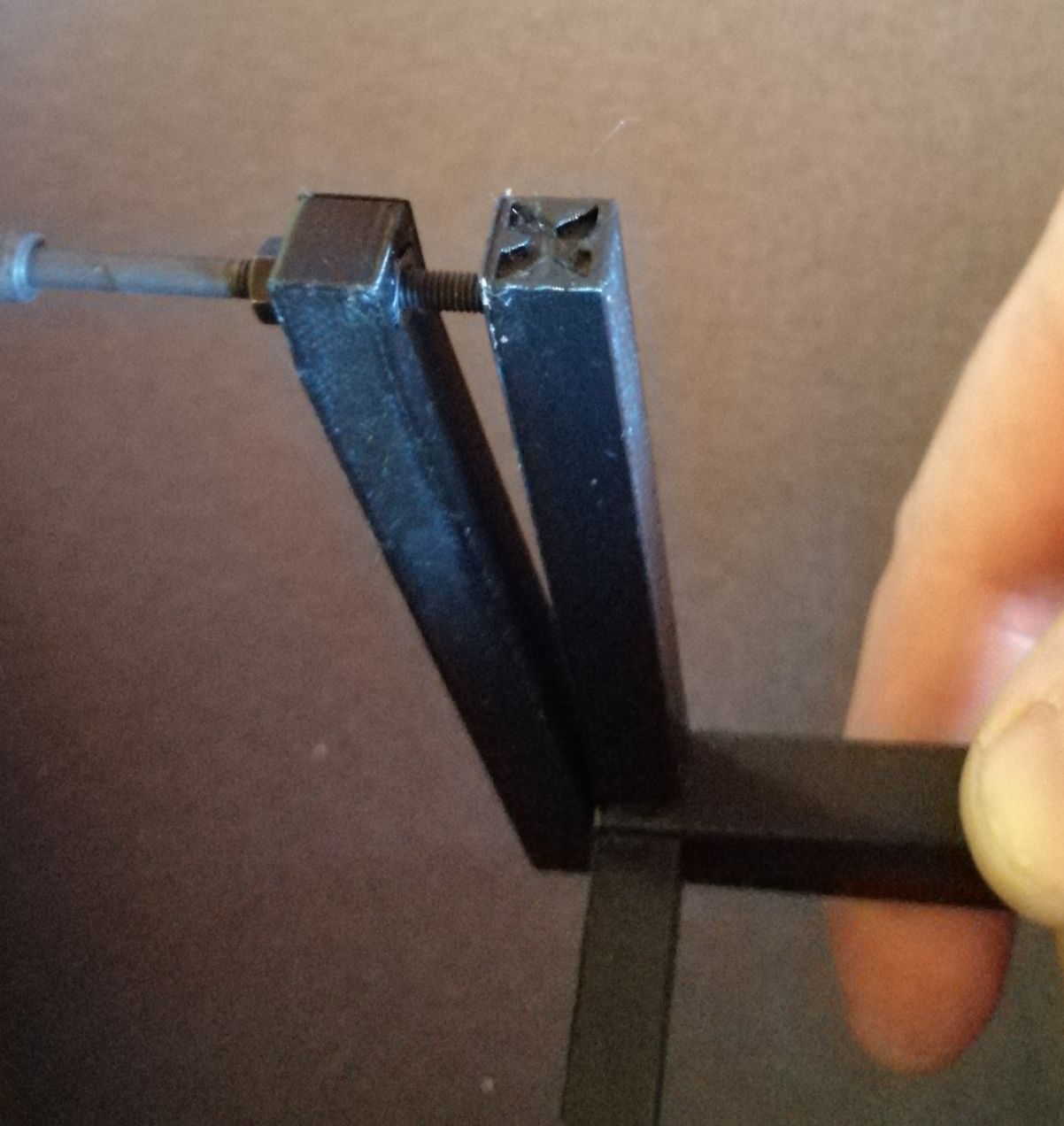
When I measuring at this position, would this difference be the X parameter?
-
This page explains it far better than I could
")
http://reprapltd.com/reprappro/documentation/ormerod-2/axis-compensation/index.html#Orthogonal_Axis_Compensation -
@Argo Thanks, i will have a look