Hi,
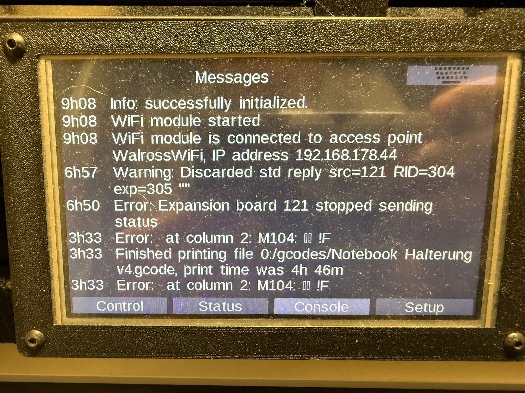
last print failed / stopped.
It seems communication with Duet tool board was lost?
The print continued and I found the extruder in it's final parking position.
After disconnecting power for a moment, everything worked again.
Both the board and tool board (1LC) run the firmware from the 3.6.0 RC1 bundle.
Error message:
Config:
;; Helpful Toolboards commands
;M115 B121 ; Show board 121
;M997 B121 ; Update tool 121
;M122 B121 ; Detailed status of toolboard
G4 S1 ; wait 1s for expansion boards to start
; General preferences
G90 ; Send absolute coordinates...
M83 ; ...but relative extruder moves
; Network
M550 P"Walross" ; Set machine name
M552 S1 ; Enable network
;*** Access point is configured manually via M587
M586 P0 S1 ; Enable HTTP
M586 P1 S1 ; Disable FTP
M586 P2 S1 ; Disable Telnet
M575 P1 S1 B57600 ; Panel Due
; Printer geometry
M669 K1 ; Select CoreXY mode
M208 X0:290 Y-3:300 Z-0.2:270 ; Axis Limits
M564 H0 ; allow unhomed movement
;------- drives from top---------------------------------------------------
; B -------+------ A
; | P.02 | P.03 |
; -------+------- Z-Drives
; | P0.1 | P0.4 |
; -------+-------
; Front
; Drive Mappings
M569 P121.0 S0 D2 ; Drive 0: E Axis
M569 P0.1 S1 D2 ; Drive 1: Z-LeftFront Axis
M569 P0.2 S0 D2 ; Drive 2: Z-LeftRear Axis
M569 P0.3 S1 D2 ; Drive 3: Z-RightRear Axis
M569 P0.4 S0 D2 ; Drive 4: Z-RightFront Axis
M569 P0.5 S1 D2 ; Drive 5: Expansion: B motor (X-axis)
M569 P0.6 S0 D2 ; Drive 6: Expansion: A motor (Y-axis)
; Motor remapping for dual Z and axis Limits
M584 X5 Y6 Z1:2:3:4 E121.0 ; Motor mapping
M671 X-60:-60:360:360 Y-10:370:370:-10 S20 ; Z leadscrews positions Left Front - Let Rear - Right Rear - Right Front
; Microstepping and Speed
M350 X32 Y32 E16 Z32 I1 ; Configure microstepping with interpolation
M92 X160.00 Y160.00 Z800.00 E682.00 ; Set steps per mm 1.8 motors
; Speeds, Acceleration and Jerk
M566 X300.00 Y300.00 Z25.00 E600.00 P1 ; Set maximum instantaneous speed changes (mm/min)
M203 X18000.00 Y18000.00 Z900.00 E7200.00 ; Set maximum speeds (mm/min) ; SpreadCycle
M201 X5000.00 Y5000.00 Z1000.00 E3000.00 ; Set accelerations (mm/s^2) ; SpreadCycle
; Motor currents
M906 X1250.00 Y1250.00 Z1100.00 E1200.00 I50 ; Set motor currents (mA) and motor idle factor in percent
M84 S30 ; Set idle timeout
; Endstops for each Axis
M574 X2 S1 P"io1.in" ; Set X endstop controlled by switch
M574 Y2 S1 P"io2.in" ; Set Y endstop controlled by switch
M574 Z1 S2 ; Set endstops controlled by probe "OLD" VINDA
;M574 Z1 S1 P"io6.in" ; Z endstop switch
; Stallgaurd Sensitivy (maybe use to pause print after crash)
M915 X S2 F0 H200 R0 ; Set X axis Sensitivity 1.8 motors
M915 Y S2 F0 H200 R0 ; Set y axis Sensitivity 1.8 motors
; Input Shaper and Accelerometer
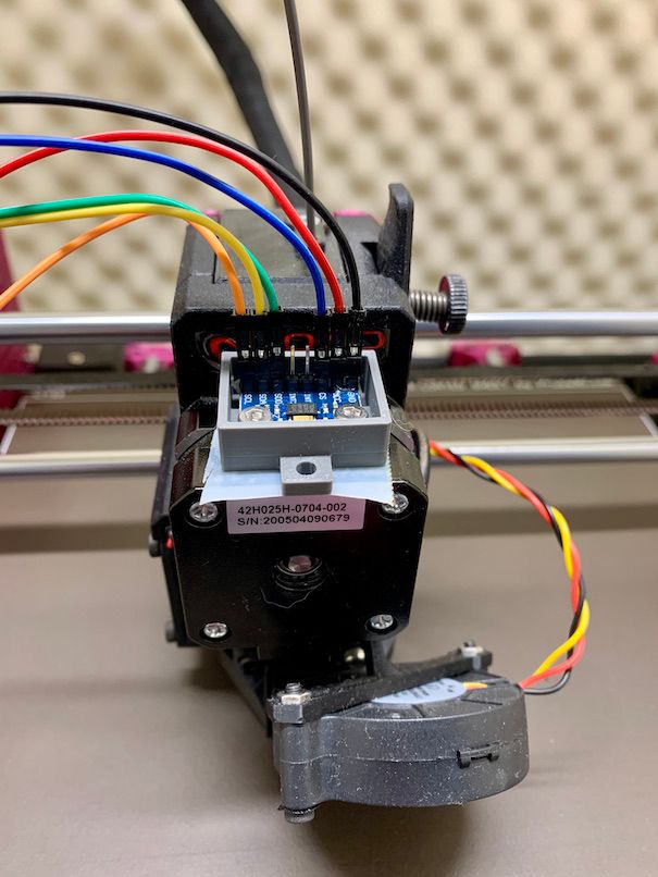
M955 P121.0 I05 ;Accelerometer
M593 P"zvdd" F50.7 S0.12
; Z-Probe
M558 P8 C"121.io2.in" I1 H1.5 F350:300 T12000 A15 S0.001 ; VINDA
; Mesh Grid
M557 X5:260 Y30:250 P7 ;
; Z Probe Offset (Probe behind Afterburner)
G31 P1000 X0 Y25 Z0.700 ; VINDA - 3DSWay Textured 0.4 nozzle
;G31 P1000 X0 Y25 Z0.580 ; VINDA - 3DSWay Textured 0.4 nozzle
; Filament Runout sensor
;M591 D0 P3 L25.95 E3 R1:900 C"121.io1.in" S1 ; Filament Sensor
; Heatbed Heaters and Thermistor Bed
M308 S0 P"temp0" Y"thermistor" T100000 B4725 C7.060000e-8 ; Heatbed Thermistor
M950 H0 C"out0" T0 Q10 ; Creates Bed Heater (SSR)
M307 H0 R0.889 K0.762:0.000 D3.02 E1.35 S0.7 B0
M140 H0 ; Bed uses Heater 0
M143 H0 S116 ; Set temperature limit for heater 0 to 115C Bed
; HotEnd Heaters and Thermistor HotEnd
M308 S1 P"121.temp0" Y"thermistor" T100000 B4725 C7.06e-8 ; define E0 temperature sensor
M950 H1 C"121.out0" T1 Q100 ; Create HotEnd Heater
M307 H1 R4.568 K0.683:0.000 D4.04 E1.35 S1.00 B0 V24.4 ; PID as heater
M143 H1 S295 ; Set temperature limit for heater 1 to 285C HotEnd
M302 S15 R15 ; min extrusion (cold extrusion) temp
; Fans Hotend + Part
M950 F3 C"121.out1" Q100 ; Creates HOTEND Fan
M106 P3 T65 L1.0 X1.0 H1 ; HOTEND Fan Settings
M950 F0 C"121.out2" Q100 ; Creates PARTS COOLING FAN
M106 P0 H-1 ; Parts Cooling Fan
; Fans Electronic compartment & Exhaust
M950 F1 C"out3" Q100 ; Creates Case Fan 1
M106 P1 T40 S170 L170 X170 H0 ; Case Fan 1 Settings
M950 F2 C"out4" Q100 ; Creates Case Fan 2
M106 P2 T40 S170 L170 X170 H0 ; Case Fan 2 Settings
M950 F5 C"out5" Q100 ; Creates Exhaust Fan
M106 P5 T82 S150 L150 X150 H0 ; Exhaust fan
; Chamber Thermistor
M308 S3 P"temp1" A"Chamber" Y"thermistor" T100000 B4725 C7.060000e-8 ; define chamber sensor
; Tools
M563 P0 D0 H1 F0 ; Define tool 0
G10 P0 X0 Y0 Z0 ; Set tool 0 axis offsets
G10 P0 R0 S0 ; Set initial tool 0 active and standby temperatures to 0C
M122 B121 after reset:
M122 B121
Diagnostics for board 121:
Duet TOOL1LC rev 1.1 or later firmware version 3.6.0-rc.1 (2025-02-28 15:03:36)
Bootloader ID: SAMC21 bootloader version 2.3 (2021-01-26b1)
All averaging filters OK
Never used RAM 7480, free system stack 140 words
Tasks: Move(3,nWait 7,0.0%,140) TMC(2,nWait 6,3.6%,52) HEAT(2,nWait 6,0.2%,110) CanAsync(5,nWait 4,0.0%,58) CanRecv(3,nWait 1,0.0%,70) CanClock(5,nWait 1,0.0%,58) ACCEL(3,nWait 6,0.0%,72) MAIN(1,running,91.4%,318) IDLE(0,ready,0.0%,26) AIN(2,delaying,4.8%,112), total 100.0%
Owned mutexes:
Last reset 01:45:08 ago, cause: power up
Last software reset time unknown, reason: AssertionFailed, available RAM 3392, slot 0
Software reset code 0x0120 ICSR 0x00000000 SP 0x2000415c Task  Freestk 129 bad marker
Stack: 00000544 00022ffc 00019b65 20003134 00016cff 20003134 000163d1 20000ed0 00000000 00000001 00008275 200071c8 200071c8 200071e0 00000000 20000f50 00011647 000223b8 00022474 00021ac8 00019b05 200071c8 200071c8 20000f50 000083ed 200071d8 000009c7
Moves scheduled 0, hiccups 0 (0.00/0.00ms), segs 0, step errors 0 (types 0x0), maxLate 0 maxPrep 0, ebfmin 0.00 max 0.00
Peak sync jitter -5/11, peak Rx sync delay 207, resyncs 0/0, no timer interrupt scheduled, next step interrupt due in 3858308480 ticks, disabled
VIN voltage: min 24.2, current 24.2, max 24.3
MCU temperature: min 36.0C, current 36.3C, max 44.9C
Driver 0: pos 0, 682.0 steps/mm, standstill, SG min 0, read errors 0, write errors 0, ifcnt 13, reads 8669, writes 13, timeouts 0, DMA errors 0, CC errors 0
Last sensors broadcast 0x00000002 found 1 91 ticks ago, 0 ordering errs, loop time 0
CAN messages queued 126204, send timeouts 0, received 55152, lost 0, ignored 0, errs 0, boc 0, free buffers 18, min 18, error reg 0
dup 0, oos 0/0/0/0, rxMotionDelay 0
Accelerometer: LIS3DH, status: 00
I2C bus errors 0, naks 3, contentions 0, other errors 0
")

")