Duet3D Logo Duet3D
    • Tags
    • Documentation
    • Order
    • Register
    • Login

    How to Control Speed of Small AC Motor

    Scheduled Pinned Locked Moved
    Duet Hardware and wiring
    6
    41
    1.8k
    Loading More Posts
    • Oldest to Newest
    • Newest to Oldest
    • Most Votes
    Reply
    • Reply as topic
    Log in to reply
    This topic has been deleted. Only users with topic management privileges can see it.
    • GoremanXundefined
      GoremanX
      last edited by GoremanX

      I have this air pump:
      https://www.amazon.com/gp/product/B08DXGQN3T

      It's AC all the way through, even internally. It's rated at 20 watts. It has a cheap inline potentiometer circuit on the load line to control its speed:

      IMG_20210227_144836.jpg

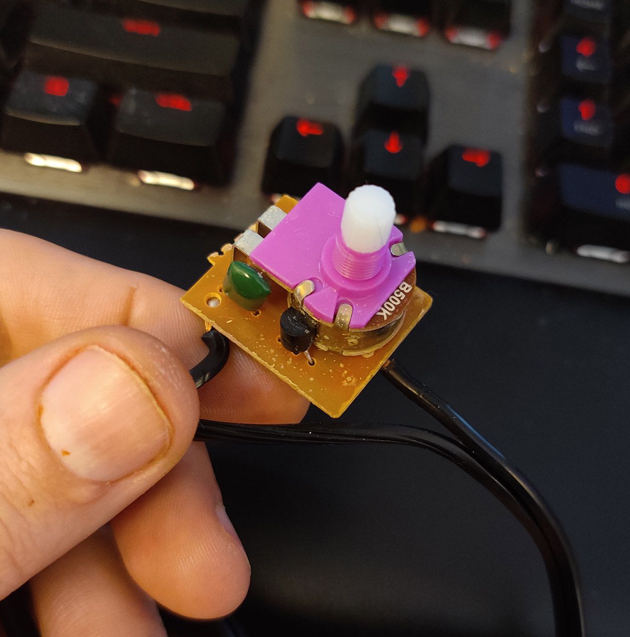
      I'd like to control the motor's speed using a Duet fan output. What's the simplest way I could go about doing that? I'm not sure what's appropriate for an AC motor such as this. It doesn't seem like a SSR would be a healthy choice, but then what do I know? Would it really be any worse than a cheap potentiometer?

      1 Reply Last reply Reply Quote 0
      • alankilianundefined
        alankilian
        last edited by

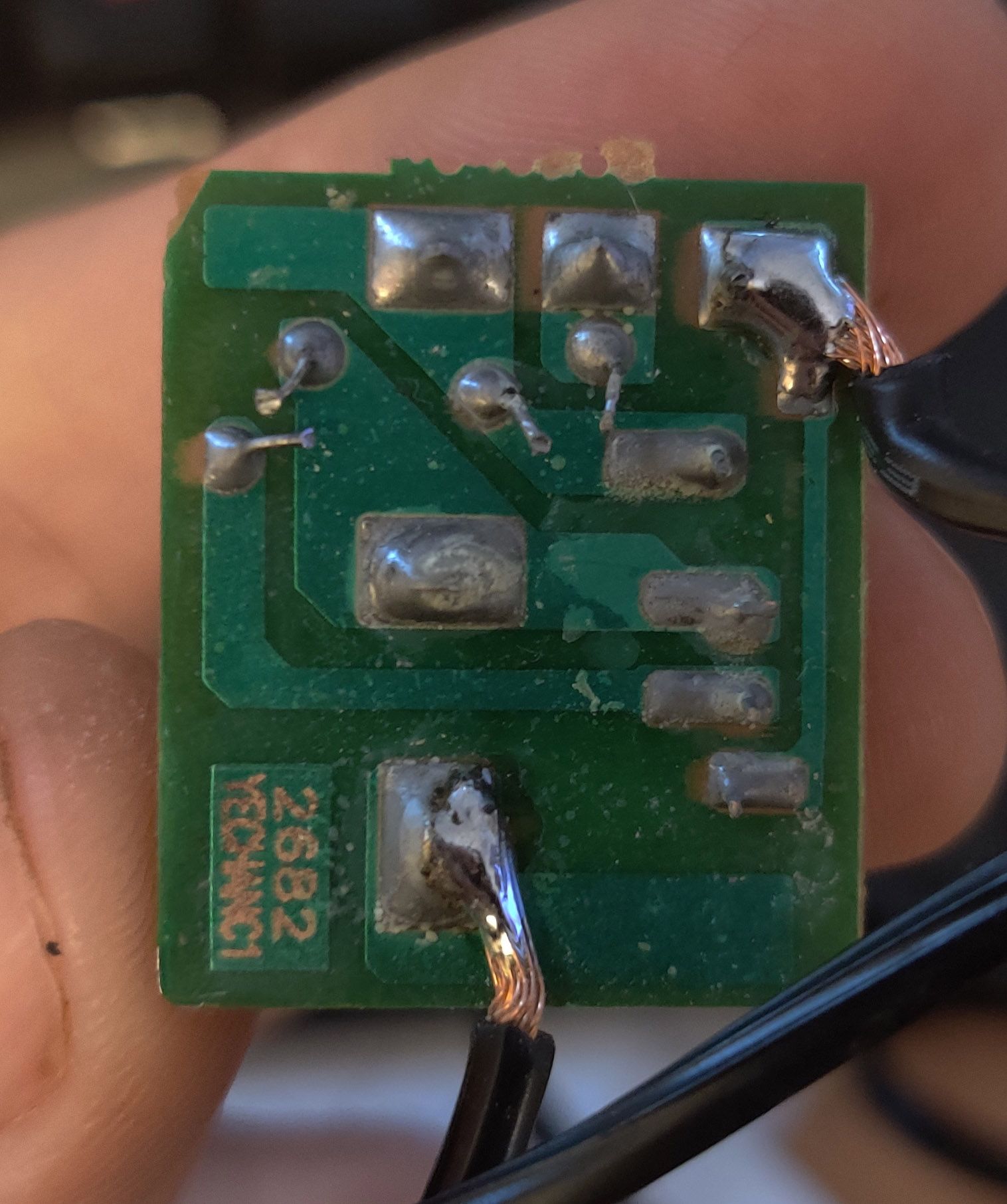
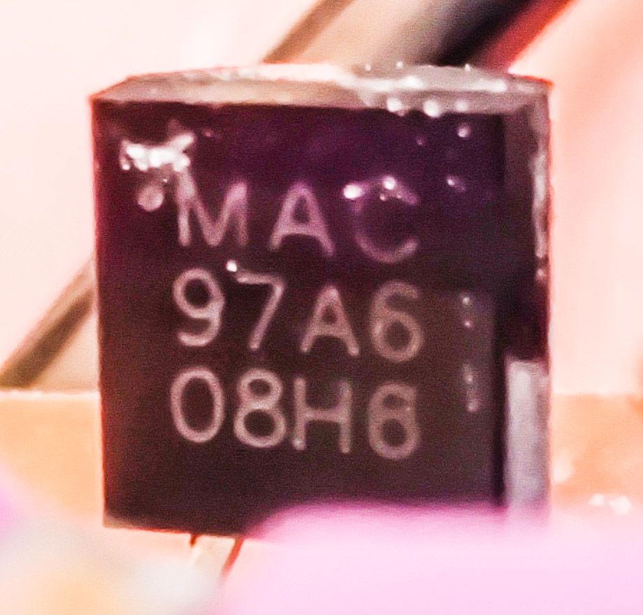
        Can you send a photo of the bottom of the circuit board as well as the number on the transistor?
        (You'll need to CAREFULLY bend it away from the potentiometer just enough to read the numbers.
        If you think you'll break it, I would not try.

        SeemeCNC Rostock Max V3 converted to V3.2 with a Duet2 Ethernet Firmware 3.2 and SE300

        GoremanXundefined 1 Reply Last reply Reply Quote 0
        • GoremanXundefined
          GoremanX @alankilian
          last edited by

          @alankilian IMG_20210227_145743.jpg IMG_20210227_145821.jpg

          1 Reply Last reply Reply Quote 0
          • alankilianundefined
            alankilian
            last edited by

            Great, I can look up that number and see it's a Triac.
            That makes sense in this circuit.
            It's a common way to "dim" AC loads.

            I'll see if I can figure out a schematic from the images next.

            SeemeCNC Rostock Max V3 converted to V3.2 with a Duet2 Ethernet Firmware 3.2 and SE300

            1 Reply Last reply Reply Quote 2
            • alankilianundefined
              alankilian
              last edited by

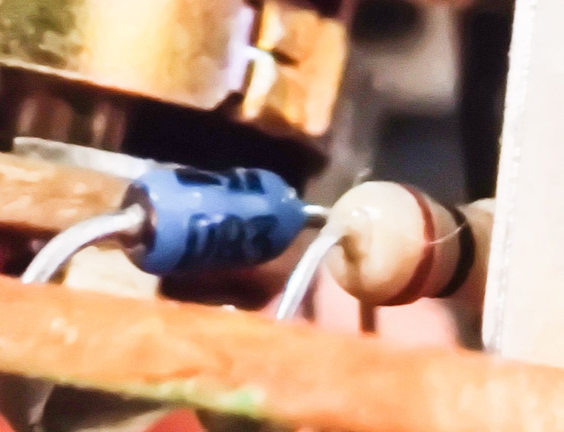
              There is a part on the other side of the potentiometer as well as underneath the potentiometer pins.

              Gan you get a shot of those parts?

              SeemeCNC Rostock Max V3 converted to V3.2 with a Duet2 Ethernet Firmware 3.2 and SE300

              GoremanXundefined 1 Reply Last reply Reply Quote 0
              • GoremanXundefined
                GoremanX @alankilian
                last edited by

                @alankilian
                IMG_20210227_151706.jpg IMG_20210227_151658.jpg IMG_20210227_151721.jpg

                I'm having a heck of a time reading the resistor, but I think it's... grey, orange, black, red? I can't measure it properly while it's in the circuit

                The blue component appears to say 083

                1 Reply Last reply Reply Quote 0
                • alankilianundefined
                  alankilian
                  last edited by alankilian

                  The two-pin ST part is probably a Diac. DB3 is close to 083.

                  That's looking pretty close to a standard phase-based Triac speed control.
                  (Which is good and bad.)

                  Grey Orange Black Red is 83 Ohms 2%
                  Red Black Orange SILVER is a 20K Ohm 10% resistor, so that's likely what it is.

                  Let me try and build a schematic.

                  SeemeCNC Rostock Max V3 converted to V3.2 with a Duet2 Ethernet Firmware 3.2 and SE300

                  1 Reply Last reply Reply Quote 0
                  • alankilianundefined
                    alankilian
                    last edited by

                    I'm pretty close, but I can't see where the wire that goes to the pump motor connects.

                    Something underneath the end of the potentiometer that doesn't have pins?

                    SeemeCNC Rostock Max V3 converted to V3.2 with a Duet2 Ethernet Firmware 3.2 and SE300

                    GoremanXundefined 1 Reply Last reply Reply Quote 0
                    • alankilianundefined
                      alankilian
                      last edited by

                      Anyway, good news bad news.

                      It's a pretty standard AC dimmer.
                      look for "Triac Phase Control" on this page to see the circuit.

                      You've got a potentiometer and a 20K Ohm resistor in series and that's why you have one extra part.

                      The bad news is that this is a good way to control AC motor power.
                      Just swapping in an SSR like for a heated bed probably won't make your pump run very well.

                      How about mounting the potentiometer to a model hobby servo and controlling it that way?

                      Is that reasonable?

                      SeemeCNC Rostock Max V3 converted to V3.2 with a Duet2 Ethernet Firmware 3.2 and SE300

                      1 Reply Last reply Reply Quote 0
                      • GoremanXundefined
                        GoremanX @alankilian
                        last edited by GoremanX

                        @alankilian The wire in the top-right corner (picture of the bottom of circuit board) goes to the motor. The wire next to the writing is the load input.

                        I was wondering if I could solder in a digital potentiometer like this: https://www.sparkfun.com/products/10613
                        in parallel with the existing pot, just kinda add wires to the existing solder at the pot pins, and have the digital pot be controlled via PWM from the fan header. That way, when the dial is set to off, the board could control it, and when the board isn't controlling it, I could still set its manually with the knob. Would that be workable?

                        1 Reply Last reply Reply Quote 0
                        • alankilianundefined
                          alankilian
                          last edited by

                          A digital pot certainly would work as a replacement for the manual pot, but you can't control a digital pot with a PWM signal.

                          It neds to have specific command sent to it to configure it and adjust it's settings.

                          SeemeCNC Rostock Max V3 converted to V3.2 with a Duet2 Ethernet Firmware 3.2 and SE300

                          GoremanXundefined 1 Reply Last reply Reply Quote 0
                          • GoremanXundefined
                            GoremanX @alankilian
                            last edited by

                            @alankilian Darn... and I can't find any PWM-controlled potentiometers. Doesn't seem like that's a common use case. I guess I could do a hobby servo to turn the knob. It's not my favorite solution, but I think it would work out pretty well. Do you have any recommendation?

                            1 Reply Last reply Reply Quote 0
                            • alankilianundefined
                              alankilian
                              last edited by alankilian

                              How far do you need to turn the knob to get the range of pressures you want?

                              Most hobby servos can turn 180-degrees.
                              Most potentiometers turn more than that, so if you can find a 180-degree range of potentiometer angles, you can just bolt on a hobby servo.
                              Luckily, you have a 3D printer and can just print something up!

                              Then, how do you want to control it from Duet?
                              GCODE from your slicer or something more automatic?

                              SeemeCNC Rostock Max V3 converted to V3.2 with a Duet2 Ethernet Firmware 3.2 and SE300

                              GoremanXundefined 1 Reply Last reply Reply Quote 0
                              • GoremanXundefined
                                GoremanX @alankilian
                                last edited by

                                @alankilian 270 degrees from completely off, but there's only 180 degrees of actual speed adjustment

                                It's my part cooling fan. I've been having a lot of trouble with part cooling when printing above 250mm/s. Accuracy is spot-on, but the heat buildup in the part is causing things to get badly warped after a few minutes. My current 6w pump isn't adequate (brushless 24v, runs right from a fan header), so I'm hoping this 20w pump will be more adequate. It certainly spews forth a ton of air.

                                I've got some old Traxxas steering boxes laying around, though I don't think they can handle much more than 6v. Ideally I could just hook a servo right up to the same 24v fan header and have it behave the same as the old pump. Though I could switch to one of the 5v outputs if absolutely necessary.

                                alankilianundefined zaptaundefined 2 Replies Last reply Reply Quote 0
                                • jay_s_ukundefined
                                  jay_s_uk
                                  last edited by

                                  which board are you connecting it to?

                                  Owns various duet boards and is the main wiki maintainer for the Teamgloomy LPC/STM32 port of RRF. Assume I'm running whatever the latest beta/stable build is

                                  GoremanXundefined 1 Reply Last reply Reply Quote 0
                                  • GoremanXundefined
                                    GoremanX @jay_s_uk
                                    last edited by

                                    @jay_s_uk Duet 3

                                    1 Reply Last reply Reply Quote 0
                                    • alankilianundefined
                                      alankilian @GoremanX
                                      last edited by

                                      @GoremanX said in How to Control Speed of Small AC Motor:

                                      Ideally I could just hook a servo right up to the same 24v fan header

                                      You are going to have to hook the servo to some source of 5 Volt power and to a nonfan output pin.

                                      THIS page shows how to hook up a hobby servo.

                                      THIS page shows how to control the angle of a hobby servo.

                                      SeemeCNC Rostock Max V3 converted to V3.2 with a Duet2 Ethernet Firmware 3.2 and SE300

                                      GoremanXundefined 1 Reply Last reply Reply Quote 0
                                      • GoremanXundefined
                                        GoremanX @alankilian
                                        last edited by

                                        @alankilian So if I'm understanding this right, I could power the servo directly from a separate 5v power supply (which I happen to already have in my printer), and then send the pwm signal from one of the IO headers, and not have to worry about protecting the board from damage with diodes?

                                        I have a servo motor here with a 300 degree sweep. Can I set M950 to an io pin rather than an output, and then just have the motor turn from, say, 5 degrees to 295 degrees by just setting the fan speed the same way I would a normal fan? I could just mount the dimmer board to a spring so the entire thing twists when the servo goes beyond the range of the pot. Or is the PWM signal not the same in servo vs fan mode?

                                        alankilianundefined 1 Reply Last reply Reply Quote 0
                                        • alankilianundefined
                                          alankilian @GoremanX
                                          last edited by

                                          @GoremanX I have never used a servo, so I'm not going to really be able to help with the controls-side of things.

                                          Don't the links I sent discuss how to control the angle of the servo from GCODE?

                                          SeemeCNC Rostock Max V3 converted to V3.2 with a Duet2 Ethernet Firmware 3.2 and SE300

                                          GoremanXundefined 1 Reply Last reply Reply Quote 0
                                          • GoremanXundefined
                                            GoremanX @alankilian
                                            last edited by

                                            @alankilian Yeah but angular motion isn't how the firmware controls fan speed. If I want part cooling to work, it looks like the part cooling fan needs to be assigned with M950 and M106, and then assigned to the appropriate tool with M563. I don't know if a servo that was assigned with M42 can be assigned to M563. In any case, M42 basically does the same thing as M106, but with preset frequencies that are appropriate to servos. So it's possible I can just replicate that with M950 Q50

                                            1 Reply Last reply Reply Quote 0
                                            • First post
                                              Last post
                                            Unless otherwise noted, all forum content is licensed under CC-BY-SA