Five bar Parallel SCARA print area problem
-
@rutku I thought about merging work modes. This is difficult, because while changing the mode, the position of the hotend changes and during the change and rotations, time is lost. So it must be while not printing and should probably be placed in the slicer, not the firmware. If the firmware decides, it will break the print process at places one doesn't wish.
I concentrate on code verification, i.e. whether the code is correct for work mode 1 for your test scenario (later for the other modes too), and improve the existing code like I describe in the other thread.
-
@joergs5 said in Five bar Parallel SCARA print area problem:
@rutku I thought about merging work modes. This is difficult, because while changing the mode, the position of the hotend changes and during the change and rotations, time is lost. So it must be while not printing and should probably be placed in the slicer, not the firmware. If the firmware decides, it will break the print process at places one doesn't wish.
It doesn't matter. I will think of something in the future. My priority is the work of the 3d printer. After working, I will understand better the codes you wrote.
@joergs5 said in Five bar Parallel SCARA print area problem:
I concentrate on code verification, i.e. whether the code is correct for work mode 1 for your test scenario (later for the other modes too), and improve the existing code like I describe in the other thread.
Yes, I'm looking forward to the result. My 11 month old baby started breaking my 3d printer. I can only debug on my small laptop. My eyes are dying. Tomorrow I will take my 3d printer to my office. I'm going to review your actions on the big monitor in my office. My eyes will be relieved. Have a nice day...

-
@rutku I am currently checking the source
- the source doesn't allow workmode change. When trying angles which are angles of a different work mode, it returns an error
- I'll iterate the angles now and write the secure coordinates you can try
-
@rutku I've found something. In L1 mode, when the angles are negative, the inverse kinematics calculates a high value for the stepper instead of a negative value.
I've inserted a test code. I don't know how you generate your code, but if you compile yourself, you can test: insert the following code into the method getInverse:
the code line before is:
thetaR = righttheta[2];
}
It's the end of the if code block which decides between cantilevered or not.if(thetaL > 270) { thetaL = thetaL - 360; //cout << " corrected thetaL, new value " << thetaL << endl; } if(thetaR > 270) { thetaR = thetaR - 360; //cout << " corrected thetaR, new value " << thetaR << endl; }the code line after is:
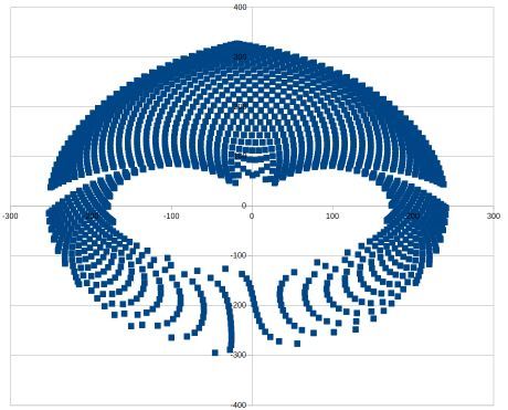
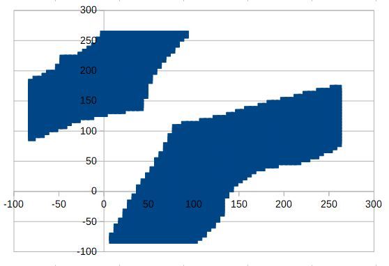
cachedX0 = x_0;I've calculated kinematics and inverse kinematics for angles between -80 and 260 degree and generated a graph in LibreOffice calc for valid values, this is the result (Y axis lines are 100 each). The graph is calculated with angles incrementing 5 degrees each between -80 and +260 degrees. The graph shows positions which are calculated as valid.
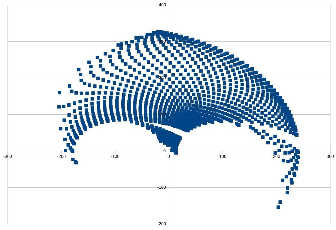
Hopes this helps with testing.
After analyzing firmware, I'll build a printer now. But if you want to test yourself, I wanted you to know my results soon.
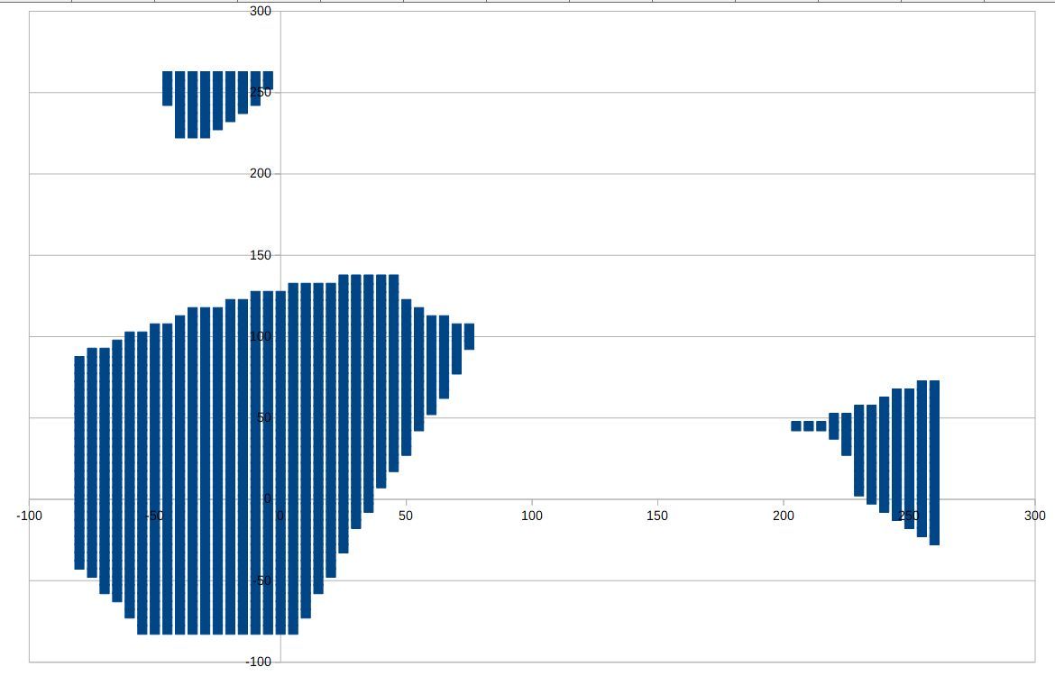
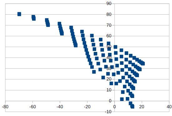
I've made a second graph, X axis is the angle of the first actuator, Y axis of the second. The points are the valid positions of the other graph:
-
config.g
M669 K9 L1 X-95:93 Y0:0 P126:133 D210:213:0:0 B51:90 A15:165:0:360:0:360 C-80:260:-80:260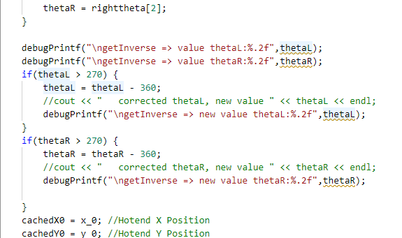
debug
G28

MotorStepsToCartesian => thetaL:220.74=MotorPosX:204064.00/StepsPermmX:924.44
MotorStepsToCartesian => thetaR:220.74=MotorPosY:83200.00/StepsPermmY:924.44
getForwad => getIntersec(distalL:210.00,distalR:213.00,xL:-190.46,yL:-82.23,xR:93.00,yR:133.00)
getIntersec firstRadius: 210.00 secondRadius: 213.00 firstX: -190.46 firstY: -82.23 secondX: 93.00 secondY: 133.00
getTurn => turn:-40677.33 = (x2:-119.27 - x1:-190.46) * (y3:133.00 - y1:-82.23) - (y2:115.33 - y1:-82.23) * (x3:93.00 - x1:-190.46)
getTurn => turn:40677.32 = (x2:18.96 - x1:-190.46) * (y3:133.00 - y1:-82.23) - (y2:-66.72 - y1:-82.23) * (x3:93.00 - x1:-190.46)
getTurn => turn:-13005.09 = (x2:-190.46 - x1:-95.00) * (y3:115.33 - y1:0.00) - (y2:-82.23 - y1:0.00) * (x3:-119.27 - x1:-95.00)
getTurn => turn:28231.32 = (x2:93.00 - x1:93.00) * (y3:115.33 - y1:0.00) - (y2:133.00 - y1:0.00) * (x3:-119.27 - x1:93.00)
getForwad => workmode:1 turnLeft:-13005.09 turnRight:28231.32
MotorStepsToCartesian => MachinePosX:nan MachinePosY:nan XYZ_AXES:3 numVisibleAxes:3
MotorStepsToCartesian => thetaL:51.00=MotorPosX:47147.00/StepsPermmX:924.44
MotorStepsToCartesian => thetaR:51.00=MotorPosY:83200.00/StepsPermmY:924.44
getForwad => getIntersec(distalL:210.00,distalR:213.00,xL:-15.71,yL:97.92,xR:93.00,yR:133.00)
getIntersec firstRadius: 210.00 secondRadius: 213.00 firstX: -15.71 firstY: 97.92 secondX: 93.00 secondY: 133.00
getTurn => turn:-23253.28 = (x2:-29.16 - x1:-15.71) * (y3:133.00 - y1:97.92) - (y2:307.49 - y1:97.92) * (x3:93.00 - x1:-15.71)
getTurn => turn:23253.28 = (x2:95.88 - x1:-15.71) * (y3:133.00 - y1:97.92) - (y2:-79.98 - y1:97.92) * (x3:93.00 - x1:-15.71)
getTurn => turn:17934.62 = (x2:-15.71 - x1:-95.00) * (y3:307.49 - y1:0.00) - (y2:97.92 - y1:0.00) * (x3:-29.16 - x1:-95.00)
getTurn => turn:16246.89 = (x2:93.00 - x1:93.00) * (y3:307.49 - y1:0.00) - (y2:133.00 - y1:0.00) * (x3:-29.16 - x1:93.00)
getForwad => workmode:1 turnLeft:17934.62 turnRight:16246.89
MotorStepsToCartesian => MachinePosX:-29.16 MachinePosY:307.49 XYZ_AXES:3 numVisibleAxes:3
MotorStepsToCartesian => thetaL:49.00=MotorPosX:45298.00/StepsPermmX:924.44
MotorStepsToCartesian => thetaR:49.00=MotorPosY:81351.00/StepsPermmY:924.44
getForwad => getIntersec(distalL:210.00,distalR:213.00,xL:-12.34,yL:95.09,xR:97.64,yR:132.92)
getIntersec firstRadius: 210.00 secondRadius: 213.00 firstX: -12.34 firstY: 95.09 secondX: 97.64 secondY: 132.92
getTurn => turn:-23641.96 = (x2:-28.62 - x1:-12.34) * (y3:132.92 - y1:95.09) - (y2:304.46 - y1:95.09) * (x3:97.64 - x1:-12.34)
getTurn => turn:23641.95 = (x2:103.61 - x1:-12.34) * (y3:132.92 - y1:95.09) - (y2:-80.00 - y1:95.09) * (x3:97.64 - x1:-12.34)
getTurn => turn:18855.43 = (x2:-12.34 - x1:-95.00) * (y3:304.46 - y1:0.00) - (y2:95.09 - y1:0.00) * (x3:-28.62 - x1:-95.00)
getTurn => turn:17578.94 = (x2:97.64 - x1:93.00) * (y3:304.46 - y1:0.00) - (y2:132.92 - y1:0.00) * (x3:-28.62 - x1:93.00)
getForwad => workmode:1 turnLeft:18855.43 turnRight:17578.94
MotorStepsToCartesian => MachinePosX:-28.62 MachinePosY:304.46 XYZ_AXES:3 numVisibleAxes:3
MotorStepsToCartesian => thetaL:51.00=MotorPosX:47147.00/StepsPermmX:924.44
MotorStepsToCartesian => thetaR:51.00=MotorPosY:81351.00/StepsPermmY:924.44
getForwad => getIntersec(distalL:210.00,distalR:213.00,xL:-15.71,yL:97.92,xR:97.64,yR:132.92)
getIntersec firstRadius: 210.00 secondRadius: 213.00 firstX: -15.71 firstY: 97.92 secondX: 97.64 secondY: 132.92
getTurn => turn:-24075.32 = (x2:-24.02 - x1:-15.71) * (y3:132.92 - y1:97.92) - (y2:307.76 - y1:97.92) * (x3:97.64 - x1:-15.71)
getTurn => turn:24075.33 = (x2:95.73 - x1:-15.71) * (y3:132.92 - y1:97.92) - (y2:-80.07 - y1:97.92) * (x3:97.64 - x1:-15.71)
getTurn => turn:17452.44 = (x2:-15.71 - x1:-95.00) * (y3:307.76 - y1:0.00) - (y2:97.92 - y1:0.00) * (x3:-24.02 - x1:-95.00)
getTurn => turn:16982.36 = (x2:97.64 - x1:93.00) * (y3:307.76 - y1:0.00) - (y2:132.92 - y1:0.00) * (x3:-24.02 - x1:93.00)
getForwad => workmode:1 turnLeft:17452.44 turnRight:16982.36
MotorStepsToCartesian => MachinePosX:-24.02 MachinePosY:307.76 XYZ_AXES:3 numVisibleAxes:3
MotorStepsToCartesian => thetaL:51.00=MotorPosX:47147.00/StepsPermmX:924.44
MotorStepsToCartesian => thetaR:51.00=MotorPosY:83200.00/StepsPermmY:924.44
getForwad => getIntersec(distalL:210.00,distalR:213.00,xL:-15.71,yL:97.92,xR:93.00,yR:133.00)
getIntersec firstRadius: 210.00 secondRadius: 213.00 firstX: -15.71 firstY: 97.92 secondX: 93.00 secondY: 133.00
getTurn => turn:-23253.28 = (x2:-29.16 - x1:-15.71) * (y3:133.00 - y1:97.92) - (y2:307.49 - y1:97.92) * (x3:93.00 - x1:-15.71)
getTurn => turn:23253.28 = (x2:95.88 - x1:-15.71) * (y3:133.00 - y1:97.92) - (y2:-79.98 - y1:97.92) * (x3:93.00 - x1:-15.71)
getTurn => turn:17934.62 = (x2:-15.71 - x1:-95.00) * (y3:307.49 - y1:0.00) - (y2:97.92 - y1:0.00) * (x3:-29.16 - x1:-95.00)
getTurn => turn:16246.89 = (x2:93.00 - x1:93.00) * (y3:307.49 - y1:0.00) - (y2:133.00 - y1:0.00) * (x3:-29.16 - x1:93.00)
getForwad => workmode:1 turnLeft:17934.62 turnRight:16246.89
MotorStepsToCartesian => MachinePosX:-29.16 MachinePosY:307.49 XYZ_AXES:3 numVisibleAxes:3
constraintsOK => cachedInvalid:0 cachedX0:0.00 cachedY0:0.00
getInverse => not cantilevered proximalL:126.00 distalL:210.00 xOrigL:-95.00 yOrigL:0.00 x_0:-29.16 y_0:307.49
getIntersec firstRadius: 126.00 secondRadius: 210.00 firstX: -95.00 firstY: 0.00 secondX: -29.16 secondY: 307.49
getTurn => turn:-17934.62 = (x2:-127.24 - x1:-95.00) * (y3:307.49 - y1:0.00) - (y2:121.80 - y1:0.00) * (x3:-29.16 - x1:-95.00)
getTurn => turn:17934.62 = (x2:-15.71 - x1:-95.00) * (y3:307.49 - y1:0.00) - (y2:97.92 - y1:0.00) * (x3:-29.16 - x1:-95.00)
getTheta => workmode: 1 thetaA:104.83 thetaB:51.00 proxturnA:-17934.62 proxturnB:-17934.62
getTheta => use: 2 x2: -15.71 y2: 97.92 thetaB: 51.00 x1: -127.24 y1: 121.80 thetaA: 104.83
getInverse => not cantilevered proximalR:133.00 distalR:213.00 xOrigR:93.00 yOrigR:0.00 x_0:-29.16 y_0:307.49
getIntersec firstRadius: 133.00 secondRadius: 213.00 firstX: 93.00 firstY: 0.00 secondX: -29.16 secondY: 307.49
getTurn => turn:-16246.89 = (x2:1.73 - x1:93.00) * (y3:307.49 - y1:0.00) - (y2:96.74 - y1:0.00) * (x3:-29.16 - x1:93.00)
getTurn => turn:16246.89 = (x2:93.00 - x1:93.00) * (y3:307.49 - y1:0.00) - (y2:133.00 - y1:0.00) * (x3:-29.16 - x1:93.00)
getTheta => workmode: 1 thetaA:133.33 thetaB:90.00 proxturnA:-16246.89 proxturnB:-16246.89
getTheta => use: 2 x2: 93.00 y2: 133.00 thetaB: 90.00 x1: 1.73 y1: 96.74 thetaA: 133.33
getInverse => value thetaL:51.00
getInverse => value thetaR:90.00
getInverse => cachedInvalid 0 cachedX0:-29.16 cachedY0:307.49 cachedX1:-29.16 cachedY1:307.49
getInverse => cachedXL:-15.71 cachedYL:97.92 cachedXR:93.00 cachedYR:133.00 cachedThetaR:90.00 cachedXR:93.00
getInverse => cachedYR:133.00 cachedThetaL:51.00 cachedXL:-15.71 cachedYL:97.92
getInverse => cachedInvalid:0 x_0:-29.16 y_0:307.49 xL:-15.71 yL:97.92 thetaL:51.00 xR:93.00 yR:133.00 thetaR:90.00 x1:-29.16 y1:307.49
constraintsOK => cachedInvalid:0 actuatorAngleLMin:-80.00<0 && thetaL:51.00>actuatorAngleLMax:260.00
constraintsOK => cachedInvalid:0 thetaL:51.00 < actuatorAngleLMin:-80.00 || thetaL:51.00 > actuatorAngleLMax:260.00 return false
constraintsOK => cachedInvalid:0 actuatorAngleRMin:-80.00<0 && thetaR:90.00>actuatorAngleRMax:260.00
constraintsOK => cachedInvalid:0 thetaR:90.00 < actuatorAngleRMin:-80.00 || thetaR:90.00 > actuatorAngleRMax:260.00 return false
getAngle => x1:-15.71 y1:97.92 x2:-29.16 y2:307.49 x3:93.00 y3:133.00
getAngle => angle:31.32 = angle2:305.00 - angle1:273.67
constraintsOK => achedInvalid:0 headAngle:31.32 < headAngleMin:15.00 || headAngle:31.32 > headAngleMax:165.00 isnan(headAngle):0 return false
getAngle => x1:-95.00 y1:0.00 x2:-15.71 y2:97.92 x3:-29.16 y3:307.49
getAngle => angle:222.67 = 360 + angle2:93.67 - angle1:231.00
constraintsOK => cachedInvalid:0 angleProxDistL:222.67 < proxDistLAngleMin:0.00 || angleProxDistL:222.67 > proxDistLAngleMax:360.00 isnan(angleProxDistL):0 return false
getAngle => x1:93.00 y1:0.00 x2:93.00 y2:133.00 x3:-29.16 y3:307.49
getAngle => angle:215.00 = 360 + angle2:125.00 - angle1:270.00
constraintsOK => cachedInvalid:0 angleProxDistR:215.00 < proxDistRAngleMin:0.00 || angleProxDistR:215.00 > proxDistRAngleMax:360.00 isnan(angleProxDistR):0 return false
constraintsOK => cachedInvalid:0 cachedX0:-29.16 cachedY0:307.49
CartesianToMotorSteps => motorPosX = cachedThetaL:51.00 * stespPermm[X_AXIS]924.44
 motorPosY = cachedThetaR:90.00 * stepsPermm[Y_AXIS]924.44
CartesianToMotorSteps => machinePos[0]:-29.16 machinePos[1]:307.49 motorPosX:0.00 motorPosY:924.44
CartesianToMotorSteps => XYZ_AXES:3 numVisibleAxes:3
constraintsOK => cachedInvalid:0 cachedX0:-29.16 cachedY0:307.49
CartesianToMotorSteps => motorPosX = cachedThetaL:51.00 * stespPermm[X_AXIS]924.44
 motorPosY = cachedThetaR:90.00 * stepsPermm[Y_AXIS]924.44
CartesianToMotorSteps => machinePos[0]:-29.16 machinePos[1]:307.49 motorPosX:0.00 motorPosY:924.44
CartesianToMotorSteps => XYZ_AXES:3 numVisibleAxes:3ok
WiFi module is connected to access point Utku, IP address 192.168.1.12
M114
X:-29.157 Y:307.490 Z:0.000 E:0.000 E0:0.0 Count 47147 83200 0 Machine -29.157 307.490 0.000 Bed comp 0.000
ok
G90 G1 H2 Y90 F200
ok
G90 G1 H2 X90 F200

MotorStepsToCartesian => thetaL:90.00=MotorPosX:83200.00/StepsPermmX:924.44
MotorStepsToCartesian => thetaR:90.00=MotorPosY:83200.00/StepsPermmY:924.44
getForwad => getIntersec(distalL:210.00,distalR:213.00,xL:-95.00,yL:126.00,xR:93.00,yR:133.00)
getIntersec firstRadius: 210.00 secondRadius: 213.00 firstX: -95.00 firstY: 126.00 secondX: 93.00 secondY: 133.00
getTurn => turn:-35633.12 = (x2:-11.42 - x1:-95.00) * (y3:133.00 - y1:126.00) - (y2:318.65 - y1:126.00) * (x3:93.00 - x1:-95.00)
getTurn => turn:35633.12 = (x2:2.68 - x1:-95.00) * (y3:133.00 - y1:126.00) - (y2:-59.90 - y1:126.00) * (x3:93.00 - x1:-95.00)
getTurn => turn:-10531.36 = (x2:-95.00 - x1:-95.00) * (y3:318.65 - y1:0.00) - (y2:126.00 - y1:0.00) * (x3:-11.42 - x1:-95.00)
getTurn => turn:13887.57 = (x2:93.00 - x1:93.00) * (y3:318.65 - y1:0.00) - (y2:133.00 - y1:0.00) * (x3:-11.42 - x1:93.00)
getForwad => workmode:1 turnLeft:-10531.36 turnRight:13887.57
MotorStepsToCartesian => MachinePosX:nan MachinePosY:nan XYZ_AXES:3 numVisibleAxes:3ok

MotorStepsToCartesian => thetaL:90.00=MotorPosX:83200.00/StepsPermmX:924.44
MotorStepsToCartesian => thetaR:90.00=MotorPosY:83200.00/StepsPermmY:924.44
getForwad => getIntersec(distalL:210.00,distalR:213.00,xL:-95.00,yL:126.00,xR:93.00,yR:133.00)
getIntersec firstRadius: 210.00 secondRadius: 213.00 firstX: -95.00 firstY: 126.00 secondX: 93.00 secondY: 133.00
getTurn => turn:-35633.12 = (x2:-11.42 - x1:-95.00) * (y3:133.00 - y1:126.00) - (y2:318.65 - y1:126.00) * (x3:93.00 - x1:-95.00)
getTurn => turn:35633.12 = (x2:2.68 - x1:-95.00) * (y3:133.00 - y1:126.00) - (y2:-59.90 - y1:126.00) * (x3:93.00 - x1:-95.00)
getTurn => turn:-10531.36 = (x2:-95.00 - x1:-95.00) * (y3:318.65 - y1:0.00) - (y2:126.00 - y1:0.00) * (x3:-11.42 - x1:-95.00)
getTurn => turn:13887.57 = (x2:93.00 - x1:93.00) * (y3:318.65 - y1:0.00) - (y2:133.00 - y1:0.00) * (x3:-11.42 - x1:93.00)
getForwad => workmode:1 turnLeft:-10531.36 turnRight:13887.57
MotorStepsToCartesian => MachinePosX:nan MachinePosY:nan XYZ_AXES:3 numVisibleAxes:3
Unfortunately something has not changed. Still in an unknown area.
-
@rutku said in Five bar Parallel SCARA print area problem:
G90 G1 H2 Y90 F200 ok G90 G1 H2 X90 F200
this is not correct, because it is working mode 2, and you start with working mode 1 (the homing position). My test proposal was not correct. After looking at the working modes in more detail, I am aware that the working mode change is not possible and my test szenario doesn't work. It has only some value to check whether rotation direction and M92 values are correct.
You can rotate with G1 H2 everywhere you want, but you're leaving the correct working mode in this case and the code says not reachable in any case where the angle positions don't match the working mode. This is checked in getForwared in the section
	// Sanity check the elbow joins to make sure it's in the correct work mode
	const float tL = getTurn(xOrigL, yOrigL, xL, yL, xDst, yDst);
	const float tR = getTurn(xOrigR, yOrigR, xR, yR, xDst, yDst);

	if ((workmode == 1 && (tL < 0 || tR < 0)) ||
		(workmode == 2 && (tL > 0 || tR < 0)) ||
		(workmode == 3 && (tL < 0 || tR > 0)) ||
		(workmode == 4 && (tL > 0 || tR > 0)))
	{
		xDst = std::numeric_limits<float>::quiet_NaN();
		yDst = std::numeric_limits<float>::quiet_NaN();
	}
It sets the result to nan if the angles are not correct. In this case the actuator 1 has the elbow of workmode 2 which means the G1 H2 has cheated changing the working mode. Technically the first actuator was going through singularity type 2 and changed mode. As a normal G1 there would be an error and the move forbidden, but G1 H2 allows all moves. I've made a step 16 in documentation to explain it.
Please make normal G1 moves after homing inside the area which is in the first graph.
-
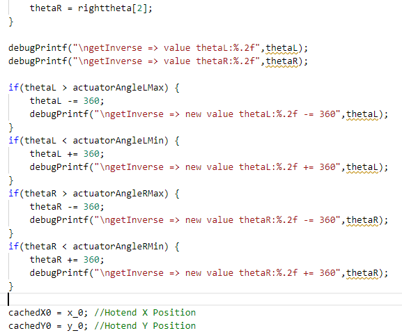
@rutku I changed the code fix to a general approach. Deciding whether the angle of the inverse kinematics is at the boundaries of the C parameter of M669, so I used those as decision point now:
if(thetaL > actuatorAngleLMax) {
	thetaL -= 360;
}
if(thetaL < actuatorAngleLMin) {
	thetaL += 360;
}
if(thetaR > actuatorAngleRMax) {
	thetaR -= 360;
}
if(thetaR < actuatorAngleRMin) {
	thetaR += 360;
}
This code is verified for L1. I have to check L2, L3, L4.
-
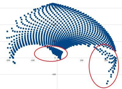
@rutku I was curious about the second graph's two small areas at top and at left - which cartesian coordinates result in those strange angles? The result:
The small area on top results in:
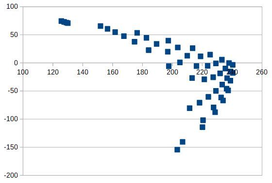
The small area on the right results in:
I.e. they are those areas:
-
@joergs5 I plotted the square about right. How to Calibration from this process step? There are spaces in the part of the pen. I will fix them and do drawing again.
square.gcode
G90
G1 X0 Y150
G1 X0 Y200
G1 X50 Y200
G1 X50 Y150
G1 X0 Y150


-
@joergs5 I have changed the way you say. I have achieved the square shape after changing the direction of the arms. I guess codes don't have hard trouble. It remains to arrange the print area.
-
-
@rutku For L2 mode (but you need a different homing position for testing this, e.g. 90 and 90 degrees) the result of the hotend coordinates is:
and the angles:
The fix works for this mode also.
-
@joergs5 Nice development. X and Y axis No access to points 0. How do I do offset?
-
@rutku your square test looks much better now!
The imperfection is IMHO due to reasons like swinging arms, hinge backlash (play which has negative results if you change direction) and similar reasons.
You can try to improve by making your test with low speed, e.g. all movements with F10 parameter. This is very slow, but should improve the result. Improving the hinges is possible by pressing the hinge to one side of the hinge with e.g. a spring with low pressure.
The somewhat wobbly line will be due to the resistance of the pen on the surface, a kind of slip stick effect. A felt-tip pen on foil will probably work better, or using fine grained paper.
-
@rutku 0,0 is not accessible due to singularity (distal arms are in opposite, straight line), this is not solvable. You can change offset by setting the X and Y coordinates of the actuators to other values (eg instead of X -95,95 set to 5,195), but this doesn't help, the singularity remains (is then at X100,Y0). Singularity are unprintable areas.
-
@rutku one hint I wanted to add: when you approach singularity areas, you will often experience that the stepper has more work to do. This may lead to lost steps, you may hear the sound of it. Result is, the firmware and actual position of the steppers doesn't fit any more. You must run homing again to set the positions right then. Lost steps often result in layer shifts, but in case of Scara the algorithm will be at the wrong place and the result wrong additionally.
-
@joergs5 said in Five bar Parallel SCARA print area problem:
The imperfection is IMHO due to reasons like swinging arms, hinge backlash (play which has negative results if you change direction) and similar reasons.
Yes, I will include the bearing on the hinges. The friction will be on the bearing.
The somewhat wobbly line will be due to the resistance of the pen on the surface, a kind of slip stick effect. A felt-tip pen on foil will probably work better, or using fine grained paper.
I want to place hotend. I want to fix it with 3D prints.
0,0 is not accessible due to singularity (distal arms are in opposite, straight line), this is not solvable. You can change offset by setting the X and Y coordinates of the actuators to other values (eg instead of X -95,95 set to 5,195), but this doesn't help, the singularity remains (is then at X100,Y0). Singularity are unprintable areas.
So how are we going to escape this singularity? How do we create a square or circle printing area?
one hint I wanted to add: when you approach singularity areas, you will often experience that the stepper has more work to do. This may lead to lost steps, you may hear the sound of it. Result is, the firmware and actual position of the steppers doesn't fit any more. You must run homing again to set the positions right then. Lost steps often result in layer shifts, but in case of Scara the algorithm will be at the wrong place and the result wrong additionally.
Is it logical to use the closed loop stepper? I took my printer to the office. I will review the codes you are writing. I will try to add things.
-
@rutku said in Five bar Parallel SCARA print area problem:
So how are we going to escape this singularity? How do we create a square or circle printing area?
The singularity cannot be escaped, you can select a printing area in the blue area of the first graph, e.g. you could select X from -100 to 100 and Y from 100 to 200. Or if you want to print a square object, X from -80 to 80 and Y from 100 to about 250. A very long object could be from X from -200 to 200 and Y from 100 to 150. A circle printing area could be a circle around the center X0Y200.
I would avoid including the two special areas which I analyzed separately, because moving there means a massive angle change, which will result in high required time and probably results in printing problems. Therefore I would limit angle 1 to below 100 and angle 2 below 150.
(all those values are for your specific configuration of actuator distance and arm lengths)
Is it logical to use the closed loop stepper?
My personal opinion, the views are somewhat controversial:
a closed loop doesn't help, it only detects lost steps better. But if you don't have a very clever recover solution, you'll have a lost print whether you use closed loop or not. Steppers without closed loops are very reliable, if you don't overload them (like near a singularity with high load, or too high microsteps with too high processing load so that the stepper doesn't receive all steps). You can check steppers by homing before every layer. This was discussed in this forum in a thread, but it requires additional print time. A discussion with different opinions was here: https://forum.duet3d.com/topic/15139/layer-shift-detection Although main focus is stepper vs servo, there is some information about closed loop and homing at every layer shift also.