Understanding Height Maps
-
@phaedrux The print was going so well but then looked like it was printing over the same extruded line and on one side the extruded plastic lifted up so it messed up. I'll try again
-
@jsinicro Maybe I needed more glue. This is a glass top I've bee using glue stick. the nozzle is set to 200 the bed is set to 85 for PLA. The nozzle is cooled via the Aqua cooled, however I do not have a blower yet for the extruded plastic That's what I am trying to print first. I've seen a bunch of videos that printing with a blower or with out one there isn't much difference.
-
Is the glass right on top of the bed heater?
Is it getting evenly hot? 85c is pretty hot for PLA.
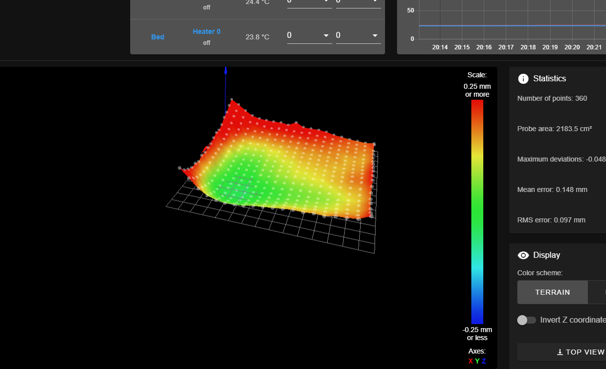
Have you run a recent G29? What does the heightmap look like?
-
@phaedrux The bed gets really hot, I could probably cook on it, the heat gets distributed evenly but its definitely hotter towards the middle. Its one peace directly on the glass with cork under it. Its the same type of glass used on stoves, custom cut.
I ran the G29 after I created the bed auto level macro in the bed.g I issue the G32 at the end of the homeall.g and then the G29. I posted that map in my other post the third one. It did not make that much difference. The pic in that post that I was seeing the light at the end of the tunnel came out decent in the beginning but then I had to pause the print as one side started becoming loose. To get to that print as the pic showed in the other post I was adjusting the nozzle height manually as I was watching it move. Not doing so the nozzle would get way to close to the bed and only extrude like a spider web. I did not load the map with that print. The map showed about 1mm difference on the points not sure why it comes out almost on a 60degree. I will run the G29 again and see if there's any difference.
-
@fcwilt Yes, both X axis can travel the full length of the Y axis bed. Currently I am focusing on getting one tower at a time to generate a relative good print, then I will try to get the other tower to do the same with different filament.
-
-
@fcwilt Your welcome, Still trying to figure out why the auto level when it moves to the first point keeps hitting the end stop, it stops once the Y axis hits the limit swatch, but the X axis limit switch lights up but the motor keeps turning till the Y axis stops.
-
Given you can only level the X gantry using two Z steppers I think you should try using these points:
- X1 = Xmin + absolute(probe X offset)
- X2 = Xmax - absolute(probe X offset)
- Y1 = ( (Ymax - absolute(probe Y offset) - (Ymin + absolute(probe Y offset) ) / 2
- Y2 = Y1
M671 X1:X2 Y1:Y2 S5
That should insure that both points probed keep the nozzle at valid positions.
Frederick
Printers: a small Utilmaker style, a small CoreXY and a E3D MS/TC setup. Various hotends. Using Duet 3 hardware running 3.4.6
-
@fcwilt Wow, here's the latest map just finished.
-
-
@fcwilt OK, thanks, I will try that. Looking at at the calculations I measured the leadscrew to the nozzle not to the probe. That's probably why it keeps hitting the endstop.
Also, The bed is supported by 2 1/8" 29.1/2"x29.1/2" aluminum sheets. The bottom sits on the center of the 2 Y axis gantries and in between the 2 sheets I have the springs -medium strength, so that I can adjust the leveling. I recently just added this I thought I could get away with out it.
-
@jsinicro: Just to make sure by absolute you mean like the abs() function correct?
-
@jsinicro said in Understanding Height Maps:
@jsinicro: Just to make sure by absolute you mean like the abs() function correct?
Yes indeed but given that the X and Y probe offsets are constants you can do the math and use the results in the M671 command.
With 3.3 firmware you can do math and have variables and if you wanted to, just for fun, you could do that math right in the gcode but it would not provide any real benefit, it would just be an exercise in using the math and variables.
Frederick
Printers: a small Utilmaker style, a small CoreXY and a E3D MS/TC setup. Various hotends. Using Duet 3 hardware running 3.4.6
-
@jsinicro said in Understanding Height Maps:
@fcwilt OK, thanks, I will try that. Looking at at the calculations I measured the leadscrew to the nozzle not to the probe. That's probably why it keeps hitting the endstop.
Also, The bed is supported by 2 1/8" 29.1/2"x29.1/2" aluminum sheets. The bottom sits on the center of the 2 Y axis gantries and in between the 2 sheets I have the springs -medium strength, so that I can adjust the leveling. I recently just added this I thought I could get away with out it.
1/8" is not very thick and if they are rolled aluminum they are likely not going to be very flat.
The preferred aluminum is cast tool plate which will have a specified flatness.
I use 1/4" but you can get it thicker, say, 4".
")
Here is a link to a supplier where you can specify the size and thickness and calculate the price:
Frederick
-
@fcwilt That's cool I did not know that, so one can put basic math functions and variables in the G-code? are there examples on this? I know there are plug-ins that one can create... First I want to focus on getting the chassis for my robotics project done.
I wen with a 1/8" as for a 1/4" of that size was twice the price, I can't recall the specs, but I picked a pretty strong and flat type it's been holding up pretty well, 1/4" would have been ideal but that was 1100 after taxes and shipping. Just did a quick price check 150 each peace wow. I got the aluminum at MetalsDepot.com
-
@jsinicro said in Understanding Height Maps:
@fcwilt That's cool I did not know that, so one can put basic math functions and variables in the G-code? are there examples on this? I know there are plug-ins that one can create... First I want to focus on getting the chassis for my robotics project done.
There is a thing in firmware 3.3 called the object model. With this you have access to just about everything about the printer.
Here are the relevant ones for the computation I mentioned in my previous post.
move.axes[0].max - holds the value for X max
move.axes[0].min - holds the value for X min

move.axes[1].max - holds the value for Y max
move.axes[1].min - holds the value for Y min

sensors.probes[0].offsets[0] - holds the value for the Z probe X offset
sensors.probes[0].offsets[1] - holds the value for the Z probe Y offset
To create the local variables needed for this computation you could:
var grid_x_min = 0
var grid_x_max = 0
var grid_y_min = 0
var grid_y_max = 0
To do the computations and set the variables you could:
set var.grid_x_min = { move.axes[0].min + abs( sensors.probes[0].offsets[0] ) }
set var.grid_x_max = { move.axes[0].max - abs( sensors.probes[0].offsets[0] ) }
set var.grid_y_min = { move.axes[1].min + abs( sensors.probes[0].offsets[1] ) }
set var.grid_y_max = { move.axes[1].max - abs( sensors.probes[0].offsets[1] ) }
Then to use the computed values in the command you could:
M671 X{var.grid_x_min}:{var.grid_x_max} Y{var.grid_y_min}:{var.grid_y_max}I wen with a 1/8" as for a 1/4" of that size was twice the price, I can't recall the specs, but I picked a pretty strong and flat type it's been holding up pretty well, 1/4" would have been ideal but that was 1100 after taxes and shipping. Just did a quick price check 150 each peace wow. I got the aluminum at MetalsDepot.com
So the two 1/8" pieces were the same price as one 1/4" piece?
Frederick
-
@jsinicro said in Understanding Height Maps:
so one can put basic math functions and variables in the G-code? are there examples on this?