Confused about fan voltage.
-
First, the obligatory stuff:
Heavily modified Ender 3 machine,
Duet 2 Wifi,
FW version: 3.2.2,
running via web interfaceI should also mention that I cut all my cables and put a DB15 cord (with the ends cut off and attached my own ends) so I can make it modular in the future, and I can just disconnect things when I'm working on the machine.
Now for my problem: Everything was working fine for a long time. I was trying to run ABS for a little while so I had the "tool fan" turned off in my slicer, although I never did get the ABS to work properly (I suspect it was because of humidity). I went to switch back to printing PLA, which had been working fine, but now I cannot get my tool fan to work. I have two (24 volt) 5015 blowers, each red wire and each black wire are connected together so there's a single 2-way plug. I have tried everything I can think of, switching it between Fan0, Fan1, and Fan2 on the Duet board, and obviously switching the relevant code in the Fans section (both M950 and M106). I left it in Fan1 because I accidentally snapped the little plastic tongue thing on Fan0 during all my testing.
Ultimately, I discovered the following: The regular hot-end fan (in always-on position 1) always has 24 volts running to the fan itself, whether the fan is plugged into my makeshift quick-connect plug or not. However, regardless of which position I put the blower fan plug on the board (Fan0, Fan1, or Fan2), it always has 2.0 volts running to it even when the tool fan is set to 0%. If I do NOT have the blower fans plugged into my quick-connect plug, and I set the tool fan control to 100%, I measure 20.4 volts... but if I do plug the fans in I still only get the 2.0 volts. I have no idea what's going on, or why I'm getting different results based on whether the blower fans are plugged in or not.
Edit: I should also point out that when I put the blower fans quick-connect plug into the quick-connect plug for the hot-end fan, they both came on at full speed, so the blowers themselves are working properly.
contents of config.g:
; Configuration file for Duet WiFi (firmware version 3) ; executed by the firmware on start-up ; ; generated by RepRapFirmware Configuration Tool v3.1.1 on Mon Jun 01 2020 01:24:07 GMT-0700 (Pacific Daylight Time) ; General preferences G90 ; send absolute coordinates... M83 ; ...but relative extruder moves M550 P"Ender 3" ; set printer name ; Network M552 S1 ; enable network M586 P0 S1 ; enable HTTP M586 P1 S0 ; disable FTP M586 P2 S0 ; disable Telnet ; Drives M569 P0 S1 ; physical drive 0 goes forwards M569 P1 S1 ; physical drive 1 goes forwards M569 P2 S0 ; physical drive 2 goes backwards M569 P3 S1 ; physical drive 3 goes forwards M569 P4 S0 ; physical drive 4 goes backwards M584 X0 Y1 Z2:4 E3 ; set drive mapping M350 X16 Y16 Z16 E16 I1 ; configure microstepping with interpolation M92 X162.24 Y160.92 Z804.32 E824.1 ; set steps per mm M203 X9000.00 Y9000.00 Z600.00 E6000.00 ; set maximum speeds (mm/min) M566 X480.00 Y480.00 Z60.00 E300.00 ; set maximum instantaneous speed changes (mm/min) aka jerk M201 X600.00 Y600.00 Z120.00 E5000.00 ; set accelerations (mm/s^2) M906 X1680 Y1680 Z1680:1680 E900 I45 ; set motor currents (mA) and motor idle factor in per cent M84 S30 ; Set idle timeout ; Axis Limits M208 X0 Y6 Z0 S1 ; set axis minima M208 X235 Y235 Z260 S0 ; set axis maxima ; Endstops M574 X1 S1 P"xstop" ; configure active-high endstop for low end on X via pin xstop M574 Y1 S1 P"ystop" ; configure active-high endstop for low end on Y via pin ystop M574 Z1 S1 P"zstop+e1stop" ; configure active-high endstops for low end on Z via pins zstop and e1stop ; Z-Probe M558 P0 H5 F120 T6000 ; disable Z probe but set dive height, probe speed and travel speed M557 X10:220 Y10:220 S20 ; define mesh grid ; Bed M308 S0 P"bedtemp" Y"thermistor" T98801 B4185 ; configure sensor 0 as thermistor on pin bedtemp M950 H0 C"bedheat" T0 ; create bed heater output on bedheat and map it to sensor 0 M140 H0 ; map heated bed to heater 0 M143 H0 S120 ; set temperature limit for heater M307 H0 R0.187 C637.8 D3.69 S1.00 V23.7 B0 ; disable bang-bang mode for the bed heater and set PWM limit ; Hotend M308 S1 P"spi.cs1" Y"rtd-max31865" ; create sensor number 1 as a PT100 sensor in the first position on the daughter board M950 H1 C"e0heat" T1 ; create nozzle heater output on e0heat and map it to sensor 1 M307 H1 R2.995 C175.4:167.5 D4.62 S1.00 V23.6 B0 ; disable bang-bang mode for heater and set PWM limit ; Fans M950 F0 C"fan1" Q500 ; create fan 0 on pin fan1 and set its frequency M106 P0 S0 H-1 ; set fan 0 value. Thermostatic control is turned off ; Tools M563 P0 S"Hotend" D0 H1 F0 ; define tool 0 G10 P0 X0 Y0 Z0 ; set tool 0 axis offsets G10 P0 R0 S0 ; set initial tool 0 active and standby temperatures to 0C ; Custom settings M572 D0 S0.08 ; set pressure advance K-factor ; Miscellaneous M911 S10 R11 P"M913 X0 Y0 G91 M83 G1 Z3 E-5 F1000" ; set voltage thresholds and actions to run on power loss T0 ; select first tool -
Which fan pin are you measuring?
One of them is tied to Vin and is always present if the power supply is on.
The other is switched to ground to control speed.
Unless you set the min speed setting in M106 the min setting is 0.1 or roughly 10%.
The 2.0 v you are measuring is likely due to that.
To test, in the M106 command where you create the fan add the parameter L0 to specify a min setting of 0.
Frederick
-
@fcwilt I freely admit I don't know a whole lot about electronics, so perhaps I'm doing this wrong? I didn't even think you could measure a single pin. This is what I've been doing: I have one of those digital multimeters with a red wire and a black wire, and you can turn the dial to select what you want to measure. I set the dial to V200 (V20 gives me an error, presumably because it's above 20), then I touch the red probe where the red wire goes, and the black probe where the black wire goes. I did this on the pins themselves, and on the tiny bit of exposed metal on the connectors (the ones I'm using to connect the fan to the DB15 wire are similar to the ones that come with the Duet for connecting to the board in that you clamp a metal piece onto the wire, then shove it into the plug, and the place where it has a little piece that clicks in to lock it leaves a tiny bit of the metal showing).
I added the L0 you mentioned to the end of my M106 line, and with the fans plugged in I got the same result as before: 2.0 volts regardless of whether it's set to 0%, 100%, or anywhere in between. The change comes when I unplug the fans. Then it registers 24.0 volts at all times, instead of the 20.4 it was registering before, again regardless of whether I have it set to 0%, 100%, or anything in between.
-
So you are measuring the 2 volts with the fan connected and you are measuring across the two terminals the fan wires are connected to?
Does the fan speed vary with the speed settings?
Frederick
Printers: a small Utilmaker style, a small CoreXY and a E3D MS/TC setup. Various hotends. Using Duet 3 hardware running 3.4.6
-
@blaidd said in Confused about fan voltage.:
I have two (24 volt) 5015 blowers, each red wire and each black wire are connected together so there's a single 2-way plug.
Photos?
The PWM fan headers switch the negative side, so you can't share the negative wires for 2 separate fans. You can share the positive wires though.
If you connect the blower directly to the fan0/fan1/fan2 headers you should be able to configure them and control them with
M950 F0 C"fan1" Q500
M106 P0 S1 H-1That should turn fan0 on full.
-
@fcwilt said in Confused about fan voltage.:
So you are measuring the 2 volts with the fan connected and you are measuring across the two terminals the fan wires are connected to?
Exactly. 2.0 volts if the blower is plugged in, 20.4 (now 24) volts if the blower is not plugged in.
Does the fan speed vary with the speed settings?
Frederick
The blower fan does not come on at all, no matter how I adjust the speed or the config settings, that is the problem.
@phaedrux said in Confused about fan voltage.:
The PWM fan headers switch the negative side, so you can't share the negative wires for 2 separate fans. You can share the positive wires though.
That's what's confusing me. It was working that way several months ago. I had the two different blower fans, with the two red wires twisted together and put together into the one hole of the plug, and the two black wires twisted together and put together into the second hole. Now, I can't get it to work, but I didn't make any changes, other than not using them for several months. I'll try to take some pictures later.
-
So it sounds like you've wired the two blowers together to a single header in parallel. What are the specs of the blowers? It's possible you've blown the fan mosfet.
https://duet3d.dozuki.com/Wiki/Connector_and_spare_part_numbers#Section_Fan_mosfet
Check the photo in that link and compare to your board.
-
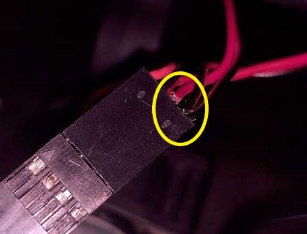
I currently have the main part taken apart, but here's the quick connect plug I mentioned.

And here is the board itself, which is in a difficult position because I built an enclosure and attached it underneath, but I don't see anything that looks melted or blown.

If there's anything you want me to zoom in on, or if you need me to temporarily pull off the duex board for my thermistor so you can see the board underneath, let me know. If you need to see the bottom of the board, I can do that too but it's going to take a bit of work to get it out.
-
@phaedrux Oh, and these are the blowers I used. I'm not sure which specs you're looking for, but hopefully it'll be on that page: https://www.amazon.com/gp/product/B0755BY9RH/ref=ppx_yo_dt_b_search_asin_title?ie=UTF8&psc=1
-
If you connect the blower directly to the fan0/fan1/fan2 headers you should be able to configure them and control them with
M950 F0 C"fan1" Q500
M106 P0 S1 H-1That should turn fan0 on full.
Have you tried that yet? Fan directly connected to the header with no additional wiring?
The fan mosfets are very small little chips near the fan headers. Get a close up well lit of the fan header area.
-
@phaedrux Even with a single blower fan plugged directly into the board, it still does not work.


-
@phaedrux Well, crap. I finally managed to take a really good picture of the area, and I'm thinking you're right, the mosfets do seem to have that black spot.

-
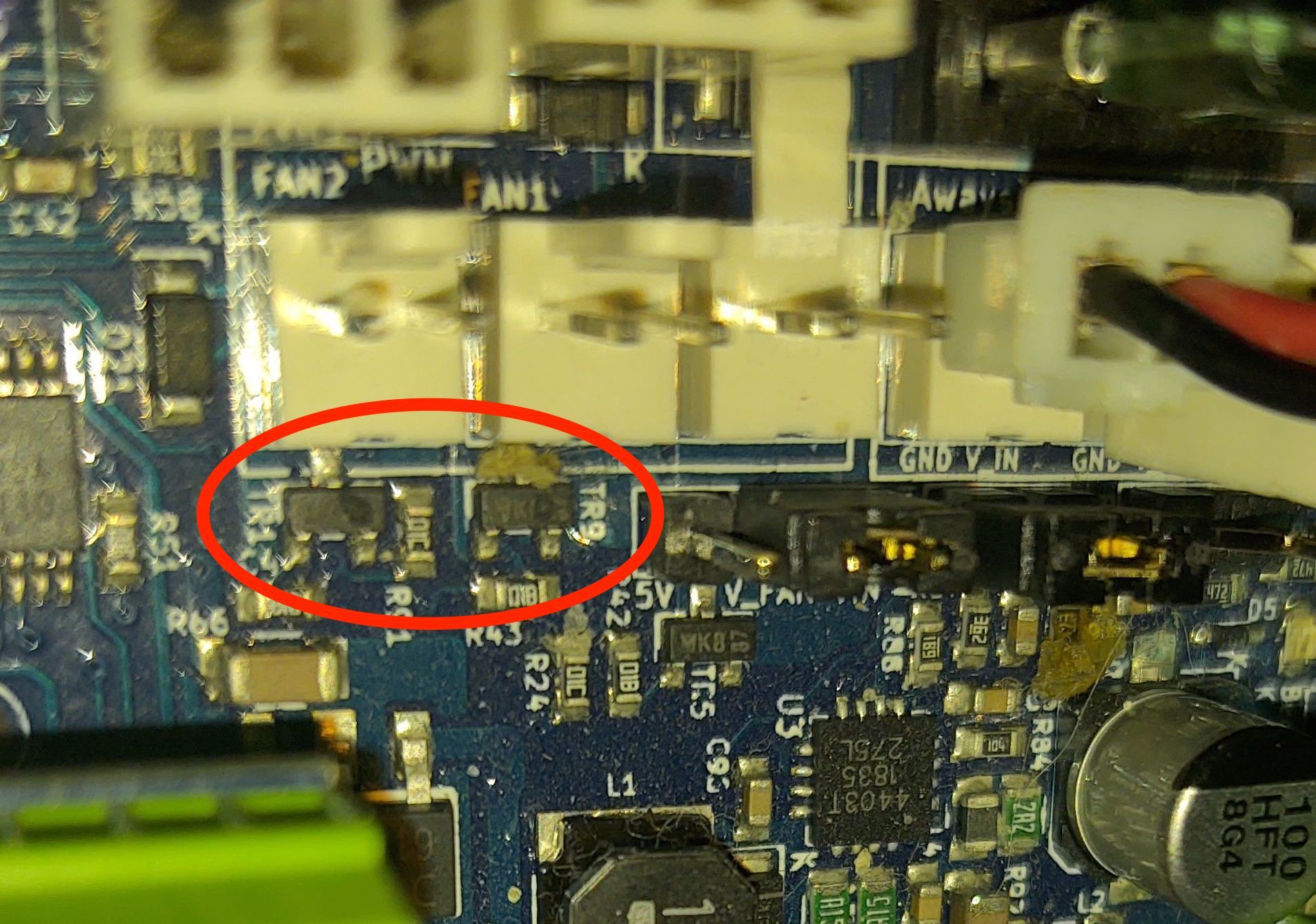 1626754679050-img_20210719_211602531.jpg
Those two mosfet chips look like they have holes blown in them just like in the example from this link.
https://duet3d.dozuki.com/Wiki/Connector_and_spare_part_numbers#Section_Fan_mosfet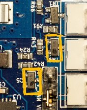
They can be replaced, but they are very small chips with 3 legs. Will depend on how handy you are with an iron. A cell phone repair shop or other electronics repair place might be able to do it. Or a local maker space?
-
I decided to replace the whole board, since I believe I short circuited something when I was doing the testing. I also broke at least one of the plastic "tongue" things, and possibly a pin, when I was doing all the plugging in and unplugging.
@phaedrux said in Confused about fan voltage.:
@blaidd said in Confused about fan voltage.:
I have two (24 volt) 5015 blowers, each red wire and each black wire are connected together so there's a single 2-way plug.
The PWM fan headers switch the negative side, so you can't share the negative wires for 2 separate fans. You can share the positive wires though.
I did have the two negative wires (and the two positive wires) connected so I could run the two blowers in parallel (one on left side, and one on right side).
![IMG_20210722_140841300[7085].jpg](/assets/uploads/files/1626988332664-img_20210722_140841300-7085-resized.jpg)
It worked for a while, but I want to be sure to do it right with the new board. I noticed when I was setting up my dual Z axis there was a way to connect them to two different pins but control them with a single command from the slicer:
M584 X0 Y1 Z2:4 E3
M574 Z1 S1 P"zstop+e1stop"
Is there any way to do the same thing with the blower fans? For example, instead of twisting the wires together, plug them individually into Fan0 and Fan1 slots, and do something like:
M950 F0 C"fan0" Q500
M950 F1 C"fan1" Q500
M563 P0 D0 H1 F0:1
For what it's worth, I intend to update the new board to the newest FW and just copy the config.g (etc) files over.
-
@blaidd Your connector can lead to a problem!
You should try to crimp them more carefully. The free thin copper wires can produce a short circuit!
-
@blaidd said in Confused about fan voltage.:
M563 P0 D0 H1 F0:1
You got it...
Exactly like in the example...
https://duet3d.dozuki.com/Wiki/Gcode#Section_M563_Define_or_remove_a_tool -
@diy-o-sphere Thanks. That helps a lot more than the only thing I had found about it, which was here: https://duet3d.dozuki.com/Wiki/Connecting_and_configuring_fans and didn't include anything about adding more than one of anything.