z-offset tool+general
-
hey
May somebody can help me with my x and y offset.
I just need some information about my general offset. I defined my tool offsets already but I need also to define an offset for driving the tool coupler into the heatbed. see pictures...may anybody can tell me which g code I can use. Also G10 or other?
Thanks a lot
R.G.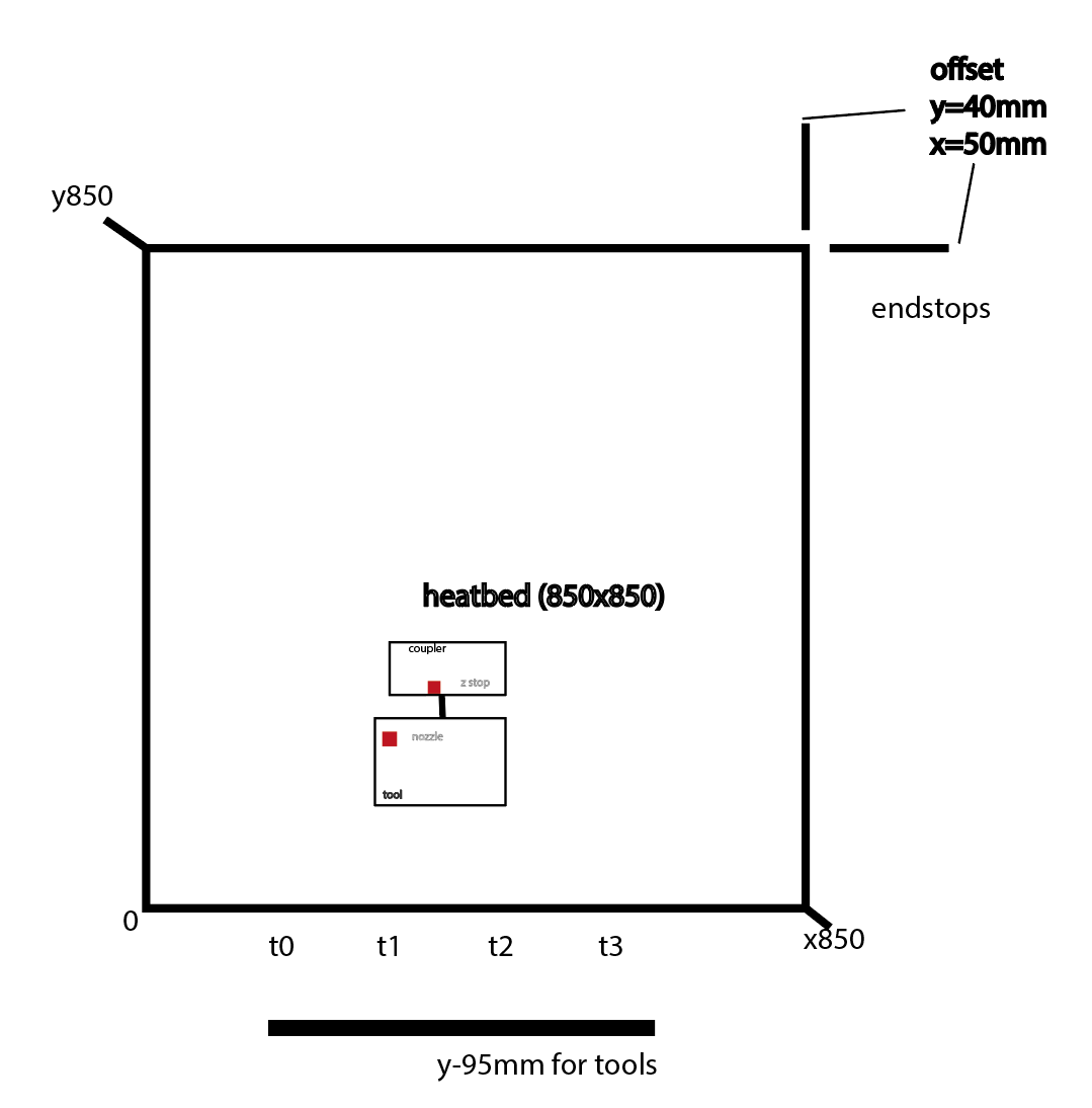
; Configuration file for Duet 3 (firmware version 3) ; executed by the firmware on start-up ; ; generated by RepRapFirmware Configuration Tool v3.2.3 on Mon Aug 02 2021 16:15:35 GMT+0200 (Mitteleuropäische Sommerzeit) ; General preferences G90 ; send absolute coordinates... M83 ; ...but relative extruder moves M550 P"Duet 3" ; set printer name M552 S1 P192.168.2.108 ; Wifi G4 S4 M574 C1 S3 M915 P1.2 C S0 F0 R1 ; Drives M569 P0.0 S1 ; physical drive 0.0 goes forwards M569 P0.1 S1 ; physical drive 0.1 goes forwards M569 P0.2 S0 ; physical drive 0.2 goes forwards M569 P0.3 S0 ; physical drive 0.2 goes forwards M569 P0.4 S0 ; physical drive 0.2 goes forwards M569 P0.5 S0 ; physical drive 0.2 goes forwards M569 P1.0 S0 ; physical drive 0.2 goes forwards M569 P1.2 S0 ; physical drive 0.2 goes forwards M569 P121.0 S1 ; physical drive 121.0 goes forwards M569 P122.0 S1 ; physical drive 122.0 goes forwards M569 P123.0 S1 ; physical drive 123.0 goes forwards M584 X1.0 Y0.0:0.1 Z0.2:0.3:0.4:0.5 C1.2 E121.0:122.0:123.0 ; set drive mapping M350 X16 Y16 Z16 E16:16:16 I1 ; configure microstepping with interpolation M92 X160.00 Y160.00 Z640.00 C91.022 E409.00:409.00:409.00 ; set steps per mm M566 X900.00 Y900.00 Z60.00 C3000 E3000.00:3000.00:3000.00 ; set maximum instantaneous speed changes (mm/min) M203 X12000.00 Y12000.00 Z6000.00 C5000 E6000.00:6000.00:6000.00 ; set maximum speeds (mm/min) M201 X500.00 Y500.00 Z300.00 C400 E250.00:250.00:250.00 ; set accelerations (mm/s^2) M906 X1300 Y1300 Z2500 C360 E1000:1000:1000 I30 ; set motor currents (mA) and motor idle factor in per cent M84 S30 ; Set idle timeout ; Axis Limits M208 X-10 Y-200 Z10 S1 ; set axis minima M208 X850 Y850 Z850 S0 ; set axis maxima ; Endstops M574 X2 S1 P"^io3.in" ; configure active-high endstop for high end on X via pin ^io3.in M574 Y2 S1 P"^io1.in" ; configure active-high endstop for high end on Y via pin ^io1.in M574 Z1 S1 P"^io2.in" ; configure active-high endstop for low end on Z via pin ^io2.in ; Z-Probe M558 P0 H-5 F300 T300 ; disable Z probe but set dive height, probe speed and travel speed M557 X10:10 Y10:10 S20 ; define mesh grid ; Heaters M308 S0 P"temp0" Y"thermistor" T100000 B4138 ; configure sensor 0 as thermistor on pin temp0 M950 H0 C"out0" T0 ; create bed heater output on out0 and map it to sensor 0 M307 H0 B0 R0.243 C586.2 D33.87 S1.00 V0 ; disable bang-bang mode for the bed heater and set PWM limit M140 H0 ; map heated bed to heater 0 M143 H0 S120 ; set temperature limit for heater 0 to 120C M308 S1 P"121.temp0" Y"thermistor" T100000 B4138 ; configure sensor 1 as PT1000 on pin 121.temp0 M950 H1 C"out1" T1 ; create nozzle heater output on out1 and map it to sensor 1 M307 H1 B0 S1.00 ; disable bang-bang mode for heater and set PWM limit M143 H1 S250 ; set temperature limit for heater 1 to 250C M308 S2 P"122.temp0" Y"pt1000" R2200 ; configure sensor 2 as PT1000 on pin 122.temp0 M950 H2 C"122.out0" T2 ; create nozzle heater output on 122.out0 and map it to sensor 2 M307 H2 B0 S1.00 ; disable bang-bang mode for heater and set PWM limit M143 H2 S250 ; set temperature limit for heater 2 to 250C M308 S3 P"123.temp0" Y"pt1000" R2200 ; configure sensor 3 as PT1000 on pin 123.temp0 M950 H3 C"123.out0" T3 ; create nozzle heater output on 123.out0 and map it to sensor 3 M307 H3 B0 S1.00 ; disable bang-bang mode for heater and set PWM limit M143 H3 S250 ; set temperature limit for heater 3 to 250C ; Fans M950 F0 C"121.out1" Q500 ; create fan 0 on pin 121.out1 and set its frequency M106 P0 S0 H-1 ; set fan 0 value. Thermostatic control is turned off M950 F1 C"121.out2" Q500 ; create fan 1 on pin 121.out2 and set its frequency M106 P1 S1 H1 T45 ; set fan 1 value. Thermostatic control is turned on M950 F2 C"122.out1" Q500 ; create fan 2 on pin 122.out1 and set its frequency M106 P2 S1 H-1 ; set fan 2 value. Thermostatic control is turned off M950 F3 C"122.out2" Q500 ; create fan 3 on pin 122.out2 and set its frequency M106 P3 S1 H2 T45 ; set fan 3 value. Thermostatic control is turned on M950 F4 C"123.out1" Q500 ; create fan 4 on pin 123.out1 and set its frequency M106 P4 S1 H-1 ; set fan 4 value. Thermostatic control is turned off M950 F5 C"123.out2" Q500 ; create fan 5 on pin 123.out2 and set its frequency M106 P5 S1 H3 T45 ; set fan 5 value. Thermostatic control is turned on M950 F6 C"out4" Q500 ; create fan 6 on pin out4 and set its frequency M106 P6 S1 H-1 ; set fan 6 value. Thermostatic control is turned off M950 F7 C"out5" Q500 ; create fan 7 on pin out5 and set its frequency M106 P7 S1 H T45 ; set fan 7 value. Thermostatic control is turned on ; Tools M563 P0 D0 H1 F0 ; define tool 0 G10 P0 X30 Y28.25 Z45 ; set tool 0 axis offsets G10 P0 R0 S0 ; set initial tool 0 active and standby temperatures to 0C M563 P1 D1 H2 F2 ; define tool 1 G10 P1 X0 Y0 Z0 ; set tool 1 axis offsets G10 P1 R0 S0 ; set initial tool 1 active and standby temperatures to 0C M563 P2 D2 H3 F4 ; define tool 2 G10 P2 X0 Y0 Z0 ; set tool 2 axis offsets G10 P2 R0 S0 ; set initial tool 2 active and standby temperatures to 0C ; Custom settings are not defined ; Miscellaneous M911 S10 R11 P"M913 X0 Y0 G91 M83 G1 Z3 E-5 F1000" ; set voltage thresholds and actions to run on power loss -
@barbarossa-cologne, you need to set it with your G31 command, I've got mine just after my M558 which is my probe assignment.
- As for measuring the offset, what I did was put a piece of paper down and brought my nozzle down until it made an indentation.
- I then brought the nozzle back up and put a dot where the mark was.
- After this, I moved the print head until my probe was directly center of the dot and the movement I needed to make was my x/y offset.
I have an IR Probe, but if you have a BLT, then put the depoyment rod directly on the dot and measure that distance moved.
Here's my Probe offset:
G31 P500 X47 Y10 Z1.514Depending on whether your 0,0 is, and it looks like you have it at the front left corner, then you would use positive numbers. But if your 0,0 is where your end stops are, then you would use negative numbers in the offset.
This is a good reference article for setting up probes as well
Hope this makes sense!
Ender 5 Plus - E3D Hemera Hotend - Duet 2 Wifi
-
@infidelprops
oik thanks for this detailed information.
yes 0,0 is at the front left. endstops back rigth.I have just a switch like the toolchanger, because it´s a custom toolchanger.
same with the tools?
this iy my tool offfset.
tool is in front of coupler (nearer to y0). So is it rigth to have a positiv number for the offset)?
Example; IN REAL. when x axis switch it at x100/y100 the nozzle is at x70/y71.75.
Thank you
R.G. -
@infidelprops
ah I think I let the Z offset at 0 when using G31, rigth?
because it´s defined in the tool offset I think ?R.G.
-
@barbarossa-cologne I had mine at 0, until I started level testing and saw that I still needed to adjust the offset a bit. That article I posted talks about it, but if you manage your offset with your tool, probably best to leave it there.
Just do lots of testing and be ready to hit the emergency stop button
-
@infidelprops
Ok.... I´ll measure the tool offsets with a mikroskope
")
Z is always problematic.So after probing x and y the axis are not moving back.... and also says it´s at 850/ 850.
Does the offset only apply when printing or did I something wrong.
I expected, that the axis moving back the offset amount.'I'm a bit confused about what code I should use. I think it's ok to define tool offset with g10 and also have a g31 for general offset, right?
thanks for your help
last steps to start printingR.G.
-
@InfidelProps
G31 P500 X47 Y10 Z1.514
How can I know the trigger value P ?R.G.
-
@barbarossa-cologne said in z-offset tool+general:
How can I know the trigger value P ?
What is the probe type? P500 is likely fine regardless.
-
@phaedrux
@InfidelProps is it still possible to help me with my offsets?
Sincd Friday I can't start my machine I've been building for 6 months