Duet3 Bed heater not working
-
I can’t seem to get the bed heater working if I trigger the bed heater the temperature never rises and the SSR light doesn’t come on. I have the SSR wired Input as positive goes to the V_out0 on duet 3 and the negative goes to the out0- port on the duet3. The load positive goes to the psu and the other side goes to the bed heater which is then grounded. The bed heater worked on my old duet WiFi board with same SSR. I used a multimeter on the v_out0 and out0- ports on the duet3 and the voltage doesn’t seem to change when the bed heater is switched on. Attached is my config… is my pin name wrong on my 950 command maybe? Also bed heater never gets warm to the touch.
; Configuration file for Duet 3 (firmware version 3) ; General preferences G90 ; send absolute coordinates... M83 ; ...but relative extruder moves M550 P"Duet 3" ; set printer name M669 K1 ; select CoreXY mode M552 S1 P0.0.0.0 ; Drives M569 P0.5 S1 ; physical drive 0.5 goes forwards M569 P0.4 S0 ; physical drive 0.4 goes forwards M569 P1.0 S1 ; physical drive 1.0 goes forwards M569 P1.1 S1 ; physical drive 1.1 goes forwards M569 P1.2 S1 ; physical drive 1.2 goes forwards M569 P0.2 S1 ; physical drive 0.2 goes backwards M569 P0.1 S1 ; physical drive 0.1 goes backwards M569 P0.0 S1 ; physical drive 0.0 goes backwards M569 P0.3 S0 ; physical drive 0.3 goes backwards M584 X0.4 Y0.5 Z1.1:1.0:1.2 E0.2:0.1:0.0 C0.3 ; set drive mapping M350 1 I0 M350 C8 I0 ; configure microstepping without interpolation M350 X16 Y16 Z16:16:16 E16:16:16 I1 ; configure microstepping with interpolation M92 X100 Y100 Z3205:3205:3205 E405:405:405 C100 ; set steps per mm M566 X1000 Y1000 Z100:100:100 E1500:1500:1500 C2 ; set maximum instantaneous speed changes (mm/min) M203 X24000 Y24000 Z900:900:900 E3600:3600:3600 C5000 ; set maximum speeds (mm/min) M201 X3000 Y3000 Z100:100:100 E1500:1500:1500 C400 ; set accelerations (mm/s^2) M906 X1400 Y1400 Z900:900:900 E1000:1000:1000 C400 I30 ; set motor currents (mA) and motor idle factor in per cent M84 S30 ; Set idle timeout ;Stall Detection - Used for homing M915 C S5 F0 H200 ; Coupler M915 X Y S5 F0 H400 ; X / Y Axes ;Leadscrew locations M671 X-43.9:-48.23:304 Y5:262:140 S25 ;Front left, Rear Left, Right S7.5 is the max correction ; Axis Limits M208 X-15 Y-20 Z0.5 S1 ; set axis minima M208 X310 Y310 Z700 S0 ; set axis maxima ; Endstops M574 X1 S3 ; configure sensorless endstop for low end on X M574 Y1 S3 ; configure sensorless endstop for low end on Y M574 Z1 S1 ; configure Z-probe endstop for high end on Z ; Z-Probe M558 P8 C"^io3.in" X0 Y0 Z1 H5 F100 T3000 ; set Z probe type to switch and the dive height + speeds G31 P500 X0 Y0 Z0 ; set Z probe trigger value, offset and trigger height M557 X30:260 Y30:260 S45 ; define mesh grid M307 H1 B0 R3.167 C154.3 D6.11 S0.50 ; Heaters M308 S0 P"temp0" Y"thermistor" T100000 B4138 ; configure sensor 0 as thermistor on pin temp0 M950 H0 C"out0" T0 ; create bed heater output on out0 and map it to sensor 0 M307 H0 B1 S1.00 ; enable bang-bang mode for the bed heater and set PWM limit M140 H0 ; map heated bed to heater 0 M143 H0 S120 ; set temperature limit for heater 0 to 120C M308 S1 P"temp1" Y"thermistor" T100000 B4138 ; configure sensor 1 as thermistor on pin temp1 M950 H1 C"out1" T1 ; create nozzle heater output on out1 and map it to sensor 1 ;307 H1 B0 S1.00 ; disable bang-bang mode for heater and set PWM limit M307 H1 B0 R3.167 C154.3 D6.11 S0.50 M143 H1 S300 ; set temperature limit for heater 1 to 300C M308 S2 P"temp2" Y"thermistor" T100000 B4138 ; configure sensor 2 as thermistor on pin temp2 M950 H2 C"out2" T2 ; create nozzle heater output on out2 and map it to sensor 2 M307 H2 B0 S1.00 ; disable bang-bang mode for heater and set PWM limit M143 H2 S300 ; set temperature limit for heater 2 to 300C M308 S3 P"temp3" Y"thermistor" T100000 B4138 ; configure sensor 3 as thermistor on pin temp3 M950 H3 C"out3" T3 ; create nozzle heater output on out3 and map it to sensor 3 M307 H3 B0 S1.00 ; disable bang-bang mode for heater and set PWM limit M143 H3 S300 ; set temperature limit for heater 3 to 300C ; Fans M950 F0 C"out4" Q500 ; create fan 0 on pin out4 and set its frequency M106 P0 C"HotEnd0Always" S1 H-1 ; set fan 0 name and value. Thermostatic control is turned off M950 F1 C"out5" Q500 ; create fan 1 on pin out5 and set its frequency M106 P1 C"HotEnd1Always" S1 H-1 ; set fan 1 name and value. Thermostatic control is turned off M950 F2 C"out6" Q500 ; create fan 2 on pin out6 and set its frequency M106 P2 C"HotEnd2Always" S1 H-1 ; set fan 2 name and value. Thermostatic control is turned off M950 F3 C"1.out6" Q500 ; create fan 3 on pin 1.out6 and set its frequency M106 P3 C"HotEnd0Temp" S0 H1 T45 ; set fan 3 name and value. Thermostatic control is turned on M950 F4 C"1.out7" Q500 ; create fan 4 on pin 1.out7 and set its frequency M106 P4 C"HotEnd1Temp" S0 H2 T45 ; set fan 4 name and value. Thermostatic control is turned on M950 F5 C"1.out8" Q500 ; create fan 5 on pin 1.out8 and set its frequency M106 P5 C"HotEnd2Temp" S0 H3 T45 ; set fan 5 name and value. Thermostatic control is turned on ; Tools M563 P0 S"HotEnd0" D0 H1 F0 ; define tool 0 G10 P0 X0 Y0 Z-5.7 ; set tool 0 axis offsets G10 P0 R0 S0 ; set initial tool 0 active and standby temperatures to 0C M563 P1 S"HotEnd1" D1 H2 F1 ; define tool 1 G10 P1 X0 Y0 Z-6.12 ; set tool 1 axis offsets G10 P1 R0 S0 ; set initial tool 1 active and standby temperatures to 0C M563 P2 S"HotEnd2" D2 H3 F2 ; define tool 2 G10 P2 X0 Y0 Z0 ; set tool 2 axis offsets G10 P2 R0 S0 ; set initial tool 2 active and standby temperatures to 0C ; Custom settings are not defined ; Miscellaneous M575 P1 S1 B57600 ; enable support for PanelDue -
Can you take a photo of your actual board wiring?
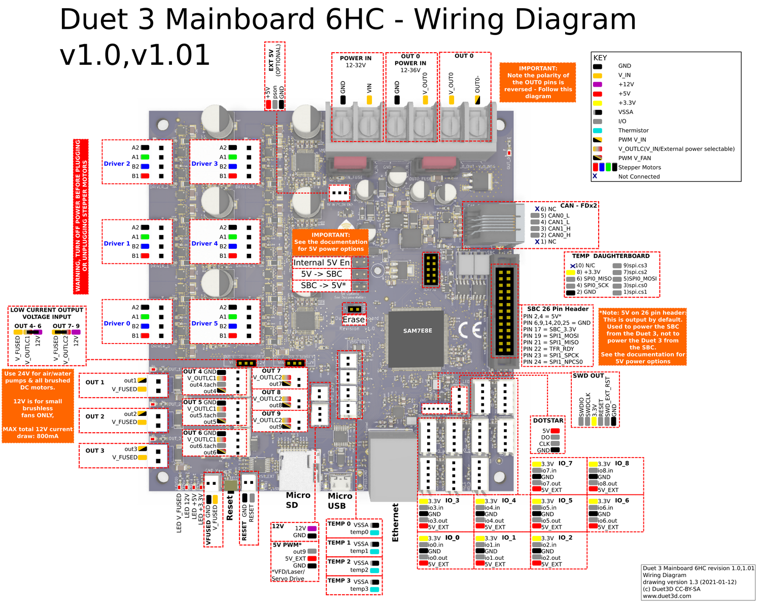
If you are using OUT_0, do you also have a voltage source going into OUT_0_INPUT? It would normally get VIN bridged over to it.
https://duet3d.dozuki.com/Wiki/Duet_3_Mainboard_6HC_Wiring_Diagram
The separate OUT0 Power in allows for a different voltage to be supplied for the OUT0 high current output (e.g for a large bed heater). If this is not required VIN power must be applied to both the POWER IN and the OUT0 POWER IN terminals for OUT 0 to be powered.
-
@phaedrux do I need to supply the input from the psu the SSR already has 110 going into it I am just using the duet to trigger it to turn on (if I understood this correctly) the board itself isn’t supplying the voltage.
-
@Phaedrux
It is wired exactly like this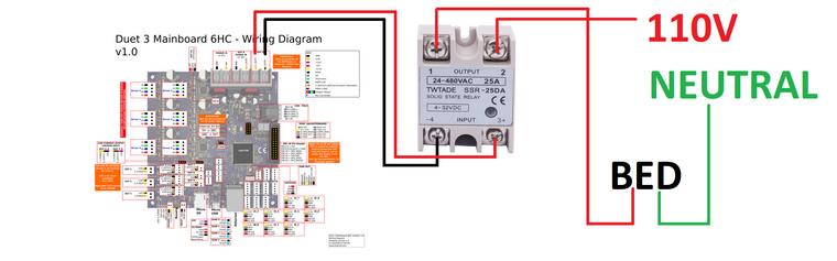 https://th.bing.com/th/id/R.18b40bc0cfbe9ea27c4958b16836aeab?rik=2r0ohUBcqSE%2F6w&pid=ImgRaw&r=0
 -
Yes, but directly to the left of OUT0 is the power source for out0. If you have nothing connected there, then out0 will have no voltage to send to the relay.
-
Typically you would just bridge the VIN from the PSU to it. So 12/24v