Duet3D 1HCL - Closed Loop Controller Beta test
-
We have a (limited number of 1HCL v0.3 prototype boards available for beta testers. I expect there will be a lot of people keen to test the boards so have made a (hopefully) quick google form here as an expression of interest.:
https://forms.gle/8iZoBE5AHdt8KnpA9As we have not yet set the price of production 1HCL boards we will charge a discounted price of £50 ex vat + P&P for the prototype boards.
Updated: The prototypes are all allocated now. thanks to everyone who responded and sorry we don't have enough for all respondents.
-
I just got my boards (they were held up in customs
 )
)This is my setup:
-
The encoder wires 5V, GND, A+,B+ and I+ are connected to the respective pins on the board. A-,B- and I- are left unconnected.
-
M569.1 P50.0 S0 T2 C2.5 E10:20 R100 I0 D0 in the config.g
After making sure every board is running the latest Beta, I followed the documentation with only minor hiccups:
-
M569.1 will require two values to be present for the Error thresholds (En.n:m.m). When given only one value, (like suggested in the documentation) it will throw an error.
-
M569.3 P50.0 reports: Error: M569.3: Command is not supported
-
After running the tuning maneuver (M569.6 P50.0 V31) The axis does not move at all or will vibrate erratically. All other axes are moving as usual.
-
The links in the documentation to the GitHub pages for the Closed Loop Plugin are not working (yet).
Cheers
Max -
@maxgyver Hi Max!
Glad to hear the boards are finally in the hands of users! I've been working on the firmware for these boards most recently, so I'll answer your points")
-
I'll investigate that at some point this week. Cheers for flagging it - for now I've just amended the documentation. I've also added in something that I don't think was clear enough before - although the 1HCL boards do support the error thresholds, I do not believe the current mainboard firmware does anything with them once they are received. This is something that's on the cards, but hasn't quite been implemented yet in the mainboard firmware.
-
Ah yes - this is an interesting one - so the
M569.3&M569.4commands haven't been added by me as a part of the 1HCL closed loop stuff - I believe they have been added by a member of the community for use on a different board entirely. The otherM569.xcommands should all state which boards they are supported on (e.g.M569.5: "Only supported for drivers on Duet 3 closed loop driver boards that are configured in closed loop mode.") I'll chase up which boardsM569.3is supported on and then add them to the docs so it's clear. We have had conversations about implementingM569.3on the 1HCL board - but it's a fair way down our roadmap right now. -
The default state for the drivers is not to move. Only after a successful full tune (
M569.6 ... V31) should they move.
This is because closed loop systems have the potential to do much worse things that open loop ones if they are configured incorrectly (e.g. if you set a negative P term it will accelerate in the opposite direction to what you want, or an I term that's too large could result in unbounded oscillation)
This means that if the axis still doesn't move after tuning, the tuning was unsuccessful - I'll walk you through what to do in this instance in a sec.
What's more concerning to me is that sometimes it vibrates erratically. It shouldn't pass tuning unless it's pretty sure it will behave. In these instances, are the PID parameters set as you describe (R100 I0 D0)? (i.e. you've not maybe increased them to see if that makes any difference?)
When a tuning move has been unsuccessful (you runM569.6 ... V31and it doesn't move), it should report back how it was unsuccesful. Although you may need to go to the console tab down the left to see the full output. Please could you let me know what it reports back after runningM569.6 ... V31and I'll talk you through what to do. If, for whatever reason,M569.6isn't reporting anything back, please could you let me know the output ofM122 B50(Assuming the board is at address 50, as you give in your example). For future reference, the docs for this should be going up soon. -
Oops, the repo is private. I'll ask someone to change that
Edit: That's been changed now, hopefully you should be able to see it
Cheers,
Louis -
-
@lirwin17 Hey Louis,
Thank you very much for our response!
3.1 The tuning maneuver appears to be successful.
G90                 	; absolute positioning
G1 Y250 X100 U300 F3000 ; Move to a known-safe position
M400                	; Wait for the move to complete
G4 P500             	; Wait for the motor to settle
M569 P50.0 D4       	; Turn closed loop back on
M569.6 P50.0 V31    	; Perform a tuning maneuver
3.2 I stuck to the standard PID values at first. I have just tried to change R value. It changes the frequency of the vibration very noticeably. The axis is moving now. But it still has very strong oscillations.
M569.1 P50.0 S0 T2 C2.5 E10:20 R10 I0 D0One more thing: What is the maximum distance/cable length between board and motor that you would recommend? My gut tells me that my 1 m cable might not be the best idea.

Cheers
Max -
Okie dokie, let's take a closed look at what it's doing. Now that the closed loop plugin should be public, please could you install that (see the getting started instructions).
Once it is installed, please could you use the following settings (but select whichever driver you are using):
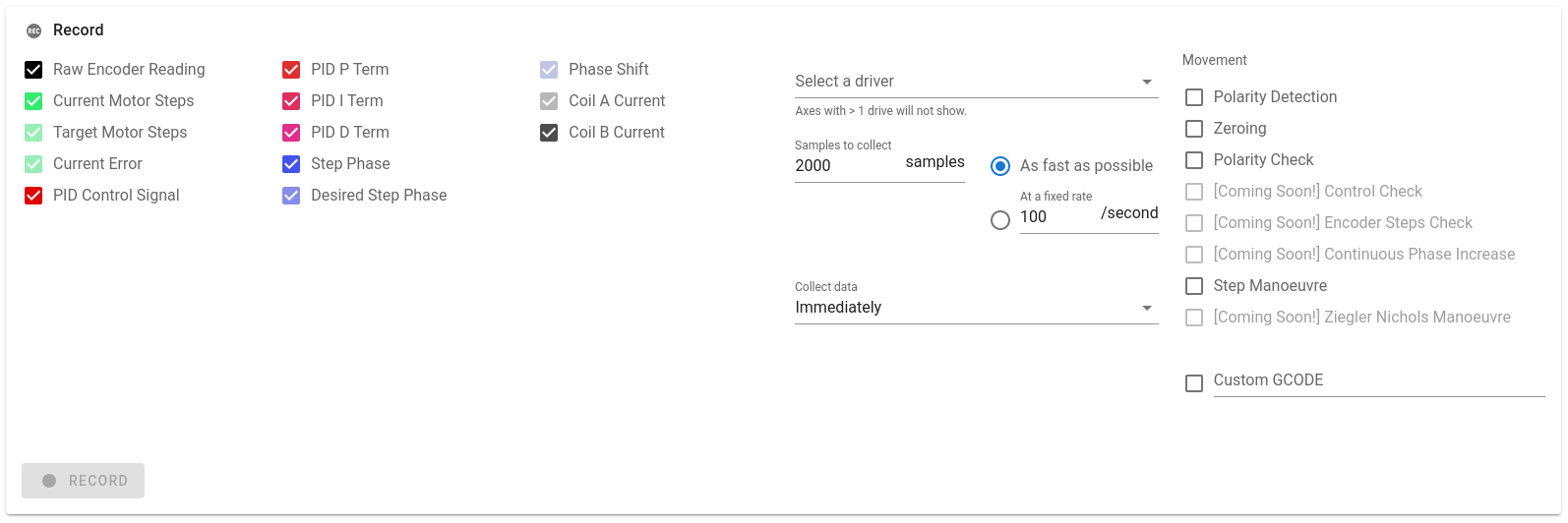
And then whilst the drive is oscillating, please press record
Once that's done, you can find the file in theclosed-loopdirectory in the system directory of your mainboard: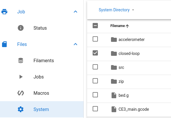
Please could you attach that csv file here and I'll have a look.WRT cable length, this may be the problem - with the recording we'll be able to see if the raw encoder reading is particularly noisy, as this may be causing the problems you're having.
@dc42 might be best placed to comment on this, but I would imagine it's much better to have a long CAN cable so the wires to the motor can be as short as possible, as opposed to vice-versa. -
Hey,
I have installed the closed loop plugin, but I can not start it. The "Start" button is greyed out" I have also tried installing alpha 0.1 with the same result. I have uninstalled all other plugins, reloaded the web interface, power cycled...
-
@maxgyver Hmm that's strange, which version of DWC are you using? You can find out by going to the General settings tab:
-
@lirwin17 I am using Duet Web Control 3.4.0-b3
Cheers
Max -
@maxgyver said in Duet3D 1HCL - Closed Loop Controller Beta test:
One more thing: What is the maximum distance/cable length between board and motor that you would recommend? My gut tells me that my 1 m cable might not be the best idea.
If the cable is that long then I recommend that you use shielded cable for the encoder. Otherwise it's quite likely that the cable will pick up interference from the stepper motor wires.
-
@maxgyver said in Duet3D 1HCL - Closed Loop Controller Beta test:
@lirwin17 I am using Duet Web Control 3.4.0-b3
That should be fixed now

Please could you re-dowload the 0.2-alpha release of the plugin, uninstall the previous plugin, and then install the new one. With any luck that should have fixed the issue. -
@dc42 I replaced my encoder cable with a shielded one (about one meter in length).
Now the vibration/noise are gone.EDIT: Nope sry, when I run a calibration maneuver (M569.6 P50.0 V31) the erratic movement of the motor is still present, independent of cable length or shielding.BTW. how do I invert the motor direction on the 1HCL, the S variable of M569.1 does nothing for me...
@lirwin17 The plugin is working now.
The motor is holding the position, but the axis is not mooving.
Cheers Max
-
@t3p3tony
I’m very interested to see where this goes! Great focus are for new board development.Are there any plans to release a full Duet 3 version or expansion boards (3 motors) eventually? The build I’m currently working on has 11 motors on it and I’m using a main board and 2 expansion (3 motor) boards to simplify wiring. I’d consider upgrading to closed loop steppers, but 11 daisy-chained boards is a bit much on the wiring and mounting side.
-
That's perfect, thankyou @maxgyver
BTW. how do I invert the motor direction on the 1HCL, the S variable of M569.1 does nothing for me...
Do you mean in open-loop or closed loop mode? I assume in open loop mode if you haven't managed to get closed loop working yet?
If that's the case, then the command to use is M569 with the S variable. (Not M569.1 as in your message )
)The motor is holding the position, but the axis is not mooving.
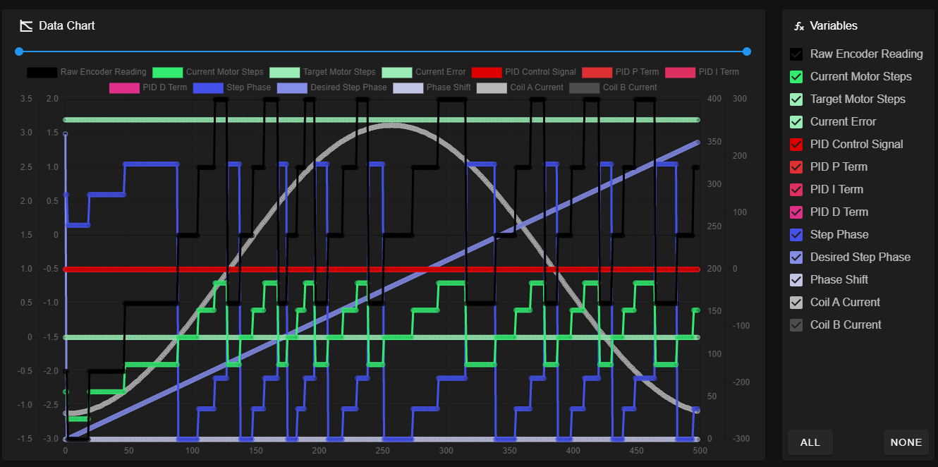
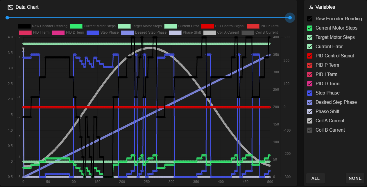
Ah! I think I know why now! Looking at the data you've sent, the relationship between
raw encoder readingandstep phaseseems to be off.
The firmware used to require you to specify Pulse Per Revolution (PPR) instead of Count Per Revolution (CPR) (Where PPR = 4 * CPR). However this was changed, and the docs updated. Looking at your data, it looks like the firmware you're using is expecting PPR, whereas the docs have told you to input CPR.
I'll investigate getting a more recent version of the firmware to you without you having to build it from source yourself, but for now, we can just specify your CPR in PPR:From your
M569.1 P50.0 S0 T2 C2.5 E10:20 R100 I0 D0, you have a C value of 2.5. This must mean that your original CPR was 2.5*200=500. (Where 200 comes from 360÷1.8, as the datasheet you linked to gives a step angle of 1.8 degrees).Knowing that your CPR is 500, your PPR must be 500*4=2000
So the required value for C is given by 2000 ÷ 200 = 10
tl;dr: Your M569.1 command should be
M569.1 P50.0 T2 C10 E10:20 R100 I0 D0Give that a go and let me know how you get on
If it still doesn't work, please could you send another data file after modifying the C value -
@tlas Its under consideration but would require a different method in hardware to read the encoders.
-
@t3p3tony
Might be a side note here, but could you look into supporting Servo motors as well (and maybe call it the “Duet 4 CNC”). I think there’s a good market capacity there in sales if you have a better integrated CNC solution than something like SmoothStepper. It would mean taking on more development scope, but I know it’s been a growing segment within the existing duet board users. As E3D and others are perusing, it’s looking like a hybrid CNC-Mill and 3D printer combos are the ‘next big thing’ in the 3D printing world.Anyway, just a thought. The closed loop capability seems like it’s 70% of the way there anyway.
-
@lirwin17 With the new C value the vibration is gone, but now the tuning maneuver reports "incorrect polarity of the driver". In open loop mode, all axes are moving as they should.
-
@maxgyver okie dokie. Looking at your raw encoder reading (the black line) it seems to be a bit all over the place. I think the next thing to check is that the encoder is doing what we think it should be doing.
I think we've both got 500 CPR from the datasheet, but I must admit the wording of it in there is a bit confusing to me:impulse/turn: 500
So unless you know any differently, I think it would be good to investigate if the CPR really is 500.
Please could you run
M122 B50and then look for theClosed loop enabled: ...line. You should see a position value on there. Take a note of that, then manually move the motor ~1 full revolution (youcanshould disconnect the motor from the board to be safe from back EMF), then do the same again. This value is in PPR, so we should expect the value to increase by around 2000.For example, my motor has a CPR of 1000 (so a PPR of 4000). When I do this, I get:
Closed loop enabled: yes, live status: 0x4, encoder type rotaryQuadrature, pre-error threshold: 10.000000, error threshold: 50.000000, reverse polarity: no, tuning: 0, tuning error: 0x1f, position -13572, raw count = 51964, collecting data: no
Closed loop enabled: yes, live status: 0x4, encoder type rotaryQuadrature, pre-error threshold: 10.000000, error threshold: 50.000000, reverse polarity: no, tuning: 0, tuning error: 0x1f, position -9633, raw count = 55903, collecting data: no
13572-9633 = 3939 ~= my 4000 PPR
[When you do this, we should expect to see ~2000 PPR] -
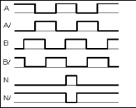
@lirwin17 This is very strange, after disconnecting the N Pin from the encoder input I get the difference of 2000 for the position value when the motor shaft is turned one revolution. When the N pin is connected, it's around 3(+-1)
-
@maxgyver the index - N or Z pin is not needed right now so i would proceed using the encoders without it.
-
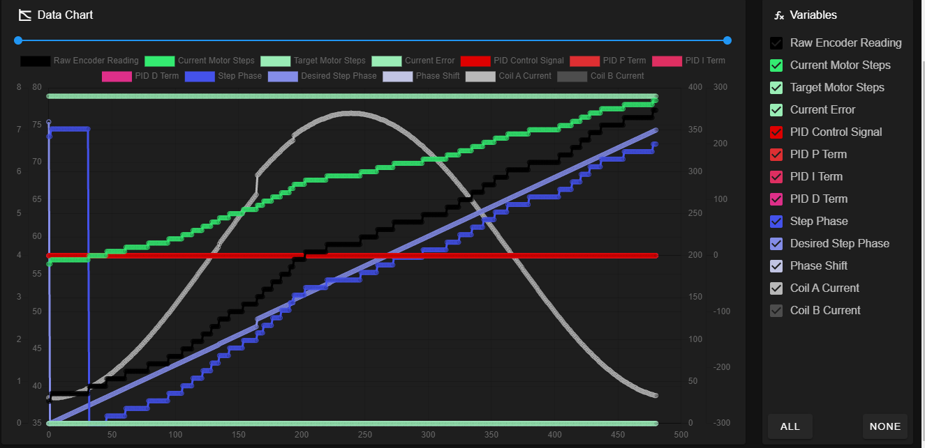
@t3p3tony Okay, this is the data chart with the N-pin disconnected