Duet3D 1HCL - Closed Loop Controller Beta test
-
Hey,
I have installed the closed loop plugin, but I can not start it. The "Start" button is greyed out" I have also tried installing alpha 0.1 with the same result. I have uninstalled all other plugins, reloaded the web interface, power cycled...
-
@maxgyver Hmm that's strange, which version of DWC are you using? You can find out by going to the General settings tab:
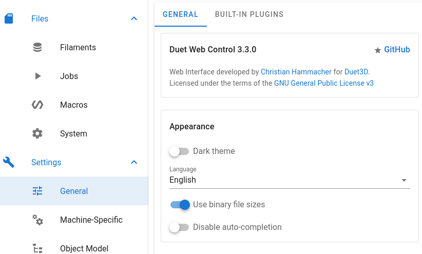
-
@lirwin17 I am using Duet Web Control 3.4.0-b3
Cheers
Max -
@maxgyver said in Duet3D 1HCL - Closed Loop Controller Beta test:
One more thing: What is the maximum distance/cable length between board and motor that you would recommend? My gut tells me that my 1 m cable might not be the best idea.
If the cable is that long then I recommend that you use shielded cable for the encoder. Otherwise it's quite likely that the cable will pick up interference from the stepper motor wires.
-
@maxgyver said in Duet3D 1HCL - Closed Loop Controller Beta test:
@lirwin17 I am using Duet Web Control 3.4.0-b3
That should be fixed now

Please could you re-dowload the 0.2-alpha release of the plugin, uninstall the previous plugin, and then install the new one. With any luck that should have fixed the issue.")
-
@dc42 I replaced my encoder cable with a shielded one (about one meter in length).
Now the vibration/noise are gone.EDIT: Nope sry, when I run a calibration maneuver (M569.6 P50.0 V31) the erratic movement of the motor is still present, independent of cable length or shielding.BTW. how do I invert the motor direction on the 1HCL, the S variable of M569.1 does nothing for me...
@lirwin17 The plugin is working now.
The motor is holding the position, but the axis is not mooving.
Cheers Max
-
@t3p3tony
I’m very interested to see where this goes! Great focus are for new board development.Are there any plans to release a full Duet 3 version or expansion boards (3 motors) eventually? The build I’m currently working on has 11 motors on it and I’m using a main board and 2 expansion (3 motor) boards to simplify wiring. I’d consider upgrading to closed loop steppers, but 11 daisy-chained boards is a bit much on the wiring and mounting side.
-
That's perfect, thankyou @maxgyver
BTW. how do I invert the motor direction on the 1HCL, the S variable of M569.1 does nothing for me...
Do you mean in open-loop or closed loop mode? I assume in open loop mode if you haven't managed to get closed loop working yet?
If that's the case, then the command to use is M569 with the S variable. (Not M569.1 as in your message )
)The motor is holding the position, but the axis is not mooving.
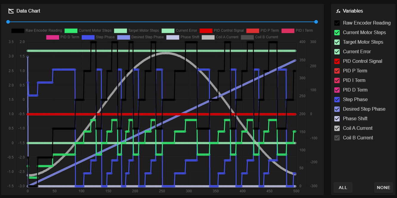
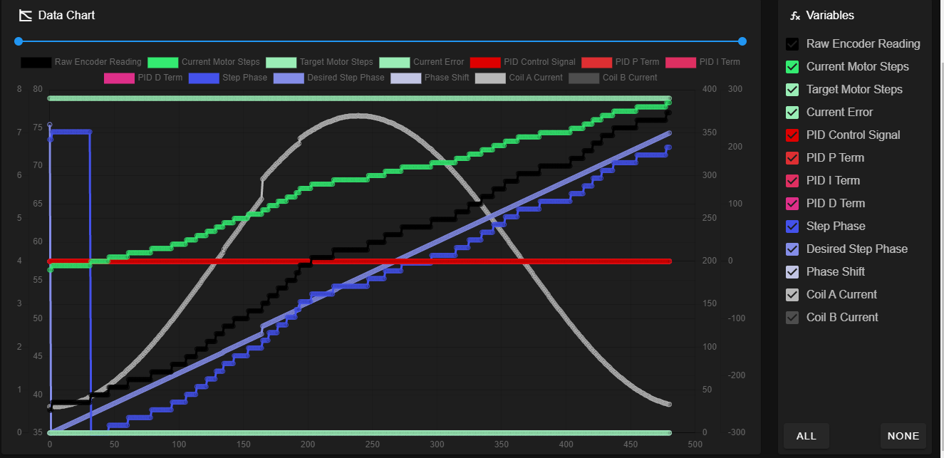
Ah! I think I know why now! Looking at the data you've sent, the relationship between
raw encoder readingandstep phaseseems to be off.
The firmware used to require you to specify Pulse Per Revolution (PPR) instead of Count Per Revolution (CPR) (Where PPR = 4 * CPR). However this was changed, and the docs updated. Looking at your data, it looks like the firmware you're using is expecting PPR, whereas the docs have told you to input CPR.
I'll investigate getting a more recent version of the firmware to you without you having to build it from source yourself, but for now, we can just specify your CPR in PPR:From your
M569.1 P50.0 S0 T2 C2.5 E10:20 R100 I0 D0, you have a C value of 2.5. This must mean that your original CPR was 2.5*200=500. (Where 200 comes from 360÷1.8, as the datasheet you linked to gives a step angle of 1.8 degrees).Knowing that your CPR is 500, your PPR must be 500*4=2000
So the required value for C is given by 2000 ÷ 200 = 10
tl;dr: Your M569.1 command should be
M569.1 P50.0 T2 C10 E10:20 R100 I0 D0Give that a go and let me know how you get on
If it still doesn't work, please could you send another data file after modifying the C value -
@tlas Its under consideration but would require a different method in hardware to read the encoders.
-
@t3p3tony
Might be a side note here, but could you look into supporting Servo motors as well (and maybe call it the “Duet 4 CNC”). I think there’s a good market capacity there in sales if you have a better integrated CNC solution than something like SmoothStepper. It would mean taking on more development scope, but I know it’s been a growing segment within the existing duet board users. As E3D and others are perusing, it’s looking like a hybrid CNC-Mill and 3D printer combos are the ‘next big thing’ in the 3D printing world.Anyway, just a thought. The closed loop capability seems like it’s 70% of the way there anyway.
-
@lirwin17 With the new C value the vibration is gone, but now the tuning maneuver reports "incorrect polarity of the driver". In open loop mode, all axes are moving as they should.
-
@maxgyver okie dokie. Looking at your raw encoder reading (the black line) it seems to be a bit all over the place. I think the next thing to check is that the encoder is doing what we think it should be doing.
I think we've both got 500 CPR from the datasheet, but I must admit the wording of it in there is a bit confusing to me:impulse/turn: 500
So unless you know any differently, I think it would be good to investigate if the CPR really is 500.
Please could you run
M122 B50and then look for theClosed loop enabled: ...line. You should see a position value on there. Take a note of that, then manually move the motor ~1 full revolution (youcanshould disconnect the motor from the board to be safe from back EMF), then do the same again. This value is in PPR, so we should expect the value to increase by around 2000.For example, my motor has a CPR of 1000 (so a PPR of 4000). When I do this, I get:
Closed loop enabled: yes, live status: 0x4, encoder type rotaryQuadrature, pre-error threshold: 10.000000, error threshold: 50.000000, reverse polarity: no, tuning: 0, tuning error: 0x1f, position -13572, raw count = 51964, collecting data: no
Closed loop enabled: yes, live status: 0x4, encoder type rotaryQuadrature, pre-error threshold: 10.000000, error threshold: 50.000000, reverse polarity: no, tuning: 0, tuning error: 0x1f, position -9633, raw count = 55903, collecting data: no
13572-9633 = 3939 ~= my 4000 PPR
[When you do this, we should expect to see ~2000 PPR] -
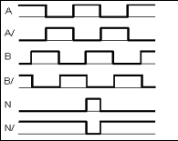
@lirwin17 This is very strange, after disconnecting the N Pin from the encoder input I get the difference of 2000 for the position value when the motor shaft is turned one revolution. When the N pin is connected, it's around 3(+-1)

-
@maxgyver the index - N or Z pin is not needed right now so i would proceed using the encoders without it.
-
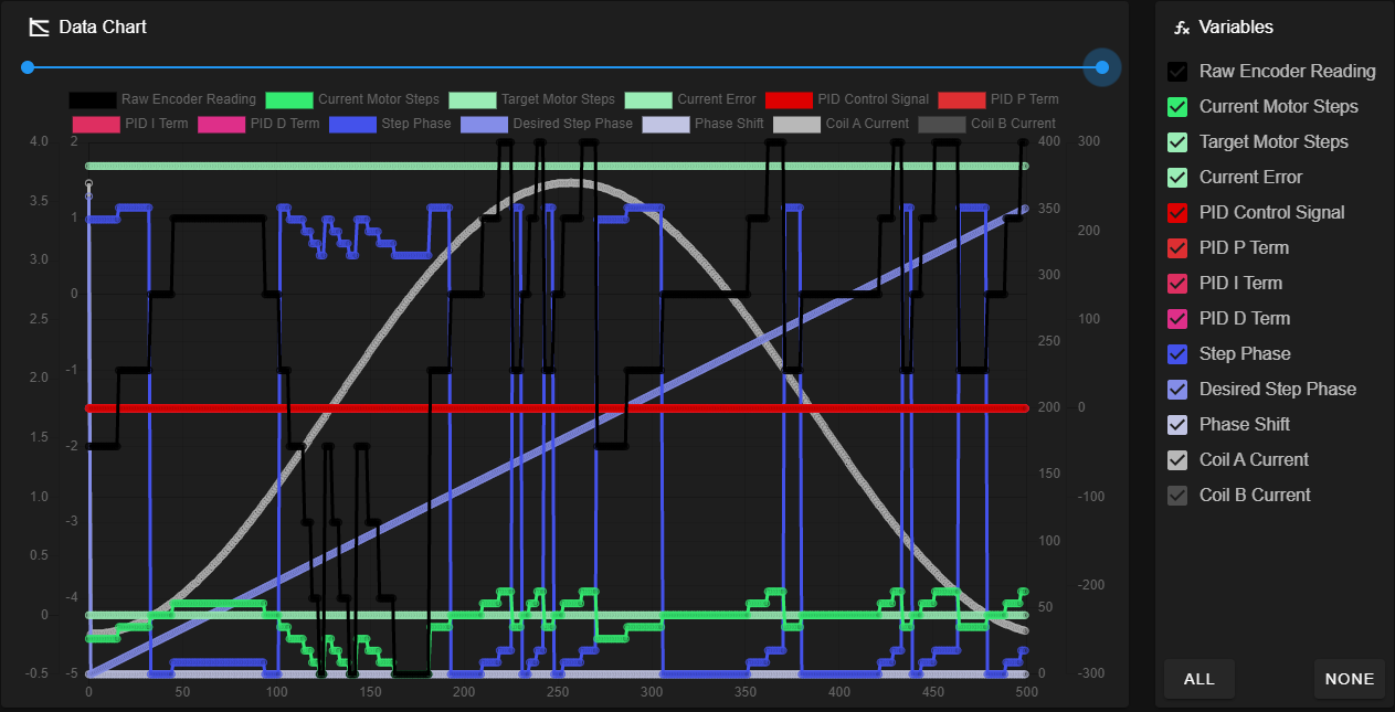
@t3p3tony Okay, this is the data chart with the N-pin disconnected
-
after disconnecting the N Pin from the encoder input I get the difference of 2000 for the position value when the motor shaft is turned one revolution. When the N pin is connected, it's around 3(+-1)
That is very strange
 Yeah, as Tony suggests that pin isn't required at the moment so I'd just leave it disconnected.
this is the data chart with the N-pin disconnected
That looks a lot better - the step phase is closely tracking the desired step phase. Is it passing tuning now? If not, there is still a fair degree of error between the two lines at points. I've often found I can decrease this error by increasing the motor current. Is your motor current set to the maximum for your motor? If not, try increasing it and see if it brings the step phase/desired step phase closer together.
-
@lirwin17 said in Duet3D 1HCL - Closed Loop Controller Beta test:
Is it passing tuning now?
Yes, it is passing the tuning. Sometimes tuning reports "incorrect polarity of the driver" first and then passes on the second try.
Is your motor current set to the maximum for your motor? If not, try increasing it and see if it brings the step phase/desired step phase closer together.
Changing the current doesn't make much of a difference.
Cheers
Max -
Okay, this is what I have tried so far:
- Quadruple checked my wiring, tried different encoder cables (long, short, with and without shielding/grounding.)
- Confirmed the CCP/PPR by turning the shaft by hand (motor disconnected) and checking the position results with M122 B50
- Disconnected all other CAN-Boards from the printer
- Disabled Input shaping
- Tried with a second 1HCL board
- Tested with a different motor
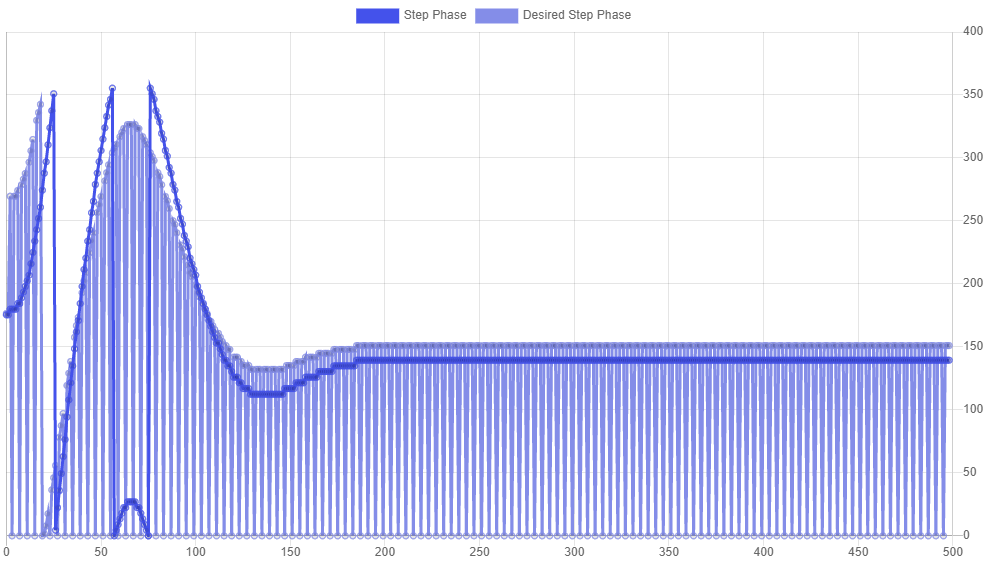
The Step Phase and desired step phase plot is still all over the place.
I have tried tuning the motor. But I get stuck at the derivative value that does not really influence the graph.
R70 I0 D0

R70 I0 D0.3
-
Hi @maxgyver ,
The Step Phase and desired step phase plot is still all over the place.
This graph looks good
Step phase basically means the current rotational position of the motor (step phase = current step position * 90 mod 360). As the motor rotates 4 steps, I would expect to see the graph you give - it increases by 360 degrees, but rolls over once due to that mod 360.
The main point aboutstep phaseis that it roughly followsdesired step phase- which it does
But I get stuck at the derivative value that does not really influence the graph.
Hmm okay, each setup will have different requirements for the D parameters - especially if an axis is particularly heavy. It might just be that you need to increase the D parameter to see an impact - but you're definitely right to start small to reduce the risk of causing unstable oscillations.
If you're worried that the D parameter is having no effect at all, you should be able to toggle on the recording of the PID control variables, so you'll be able to see the actual D value that's being calculated, and the effect it's having on the overall PID control signal. If you find that it is too small, you can increase the D value.
But do heed the warning on the tuning page:
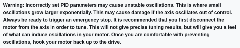
We've already had some issues with the latest beta firmware being out of date - which I won't rule out causing these issues. As promised, we've just published an 'unofficial' firmware at this dropbox link.
Feel free to install this updated firmware and see if it has any effect - but don't forget to undo the multiplication by 4 that we did on your CPR! This updated firmware works as-per the docs, so requires a CPR value for the C parameter -
HERE'S an article I wrote (oh, god, 21 years ago) about how to tune a PID system.
It's for DC servo motor with an encoder, but all the theory applies to steppers also.
It looks like you've got EXCELLENT logging and plotting ability, so you should be able to tune fairly well.
As I've said in the past, I'm not sure what people think they are going to get out of closed-loop steppers that they don't get from open-loop steppers other than recovery if you crash your head and miss a bunch of steps.
It is not going to get you better accuracy than open-loop if you are not crashing. In fact, I'd be willing to bet that accuracy goes way down to about 2 or 3 steps even when well tuned. (I'm ready and willing to be proven wrong, this is based on decades of tuning DC servos closed-loop with a lot of different mechanical systems.)