Duet3D Logo Duet3D
    • Tags
    • Documentation
    • Order
    • Register
    • Login

    Large Format Dowell to Duet conversion

    Scheduled Pinned Locked Moved
    Duet Hardware and wiring
    14
    362
    35.3k
    Loading More Posts
    • Oldest to Newest
    • Newest to Oldest
    • Most Votes
    Reply
    • Reply as topic
    Log in to reply
    This topic has been deleted. Only users with topic management privileges can see it.
    • Charles Fraserundefined
      Charles Fraser @T3P3Tony
      last edited by

      @t3p3tony

      Could it be I should send higher mA to the drives?

      ; Drives
      M569 P0.0 S1                                                    ; physical drive 0.0 goes forwards
      M569 P0.1 S1                                                    ; physical drive 0.1 goes forwards
      M569 P0.2 S1                                                    ; physical drive 0.2 goes forwards
      M569 P0.3 S1                                                    ; physical drive 0.3 goes forwards
      M569 P0.4 S1                                                    ; physical drive 0.4 goes forwards
      M569 P0.5 S1                                                    ; physical drive 0.5 goes forwards
      M569 P1.0 S1                                                    ; physical drive 1.0 goes forwards
      M584 X0.0 Y0.1 Z0.2:0.4:0.5:0.3 E1.0
      M350 X16 Y128 Z16 E16  I1                                ; configure microstepping with interpolation
      M92 X80.00 Y1280.00 Z400.00 E420.00          ; set steps per mm
      M566 X900.00 Y900.00 Z60.00 E120.00        ; set maximum instantaneous speed changes (mm/min)
      M203 X6000.00 Y6000.00 Z180.00 E1200.00 ; set maximum speeds (mm/min)
      M201 X500.00 Y500.00 Z20.00 E250.00        ; set accelerations (mm/s^2)
      M906 X2800 Y2800 Z1200 E1200 I30                      ; set motor currents (mA) and motor idle factor in per cent
      M84 S30                                                         ; Set idle timeout
      
      T3P3Tonyundefined 1 Reply Last reply Reply Quote 0
      • T3P3Tonyundefined
        T3P3Tony administrators @Charles Fraser
        last edited by

        @charles-fraser it could be, where did those values come from originally? What Z motors do you have? also are you sure your Z steps/mm are right?

        www.duet3d.com

        Charles Fraserundefined 1 Reply Last reply Reply Quote 0
        • Charles Fraserundefined
          Charles Fraser @T3P3Tony
          last edited by Charles Fraser

          @t3p3tony

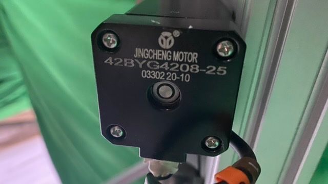
          I just took standard NEMA17 1.6A power rating

          The actual motor spec I can't find anywhere:

          FC0444B4-A9FA-4970-B2CB-538C5CAEB69D.jpeg

          24F7875F-0297-4952-9242-6714B17A94E3.jpeg

          It's a screw with a lead of 5mm. It's defo not moving if I put +100 or +0.1 so is it really an issue with steps per mm ?

          T3P3Tonyundefined 1 Reply Last reply Reply Quote 0
          • T3P3Tonyundefined
            T3P3Tony administrators @Charles Fraser
            last edited by

            @charles-fraser said in Large Format Dowell to Duet conversion:

            is it really an issue with steps per

            assuming the gearing of those pulleys is 1.8:1 then 400 is correct I think. Other wise is probably not so far of that nothing moves when you only move 0.1mm in ZWithe the power turned off can you disconnect a Z motor and check the continuity of the two coils with a multi meter. Of the the 4 pins on the plug that you are plugging into the duet there should be two pairs of wires with low resistance.

            www.duet3d.com

            Charles Fraserundefined 1 Reply Last reply Reply Quote 0
            • Charles Fraserundefined
              Charles Fraser @T3P3Tony
              last edited by

              @t3p3tony

              Hi Tody I checked the pairs when wiring but I will double check now

              T3P3Tonyundefined 1 Reply Last reply Reply Quote 0
              • T3P3Tonyundefined
                T3P3Tony administrators @Charles Fraser
                last edited by

                @charles-fraser if the two pairs are pins 1-2 and pins 3-4 for the Z motors then the next step is to see if the motors turn individually, without the belts connected.

                www.duet3d.com

                Charles Fraserundefined 5 Replies Last reply Reply Quote 0
                • Charles Fraserundefined
                  Charles Fraser @T3P3Tony
                  last edited by

                  @t3p3tony

                  yup the pairs are pins 1+2 and 3+4

                  so I loosened the belt and stuck a sticker atop the motor so I can see it spinning and it does spin now the tension is off the belt.

                  1 Reply Last reply Reply Quote 0
                  • Charles Fraserundefined
                    Charles Fraser @T3P3Tony
                    last edited by

                    @t3p3tony it just sounds like the one z motor is trying to move though

                    1 Reply Last reply Reply Quote 0
                    • Charles Fraserundefined
                      Charles Fraser @T3P3Tony
                      last edited by

                      @t3p3tony

                      It seems to be working now πŸ™‚

                      I'll try and work out steps per mm

                      1 Reply Last reply Reply Quote 0
                      • Charles Fraserundefined
                        Charles Fraser @T3P3Tony
                        last edited by

                        @t3p3tony

                        Okay +50 takes it +10 closer to the nozzle, i.e the bed goes up. I'm pretty sure we want + to make the bed go father from the nozzle right? Anyway, I will times the steps per mm by 5

                        T3P3Tonyundefined 1 Reply Last reply Reply Quote 0
                        • Charles Fraserundefined
                          Charles Fraser @T3P3Tony
                          last edited by

                          @t3p3tony

                          Okay it repeatedly shows it’s just going beyond 50mm when I send 50mm

                          4272C2F6-E40A-4D5D-A717-31D0C9198BF1.jpeg

                          1 Reply Last reply Reply Quote 0
                          • T3P3Tonyundefined
                            T3P3Tony administrators @Charles Fraser
                            last edited by

                            @charles-fraser said in Large Format Dowell to Duet conversion:

                            I'm pretty sure we want + to make the bed go father from the nozzle right?

                            yes Z+ should increase the gap between the nozzle and the Bed. this is controlled with the S parameter in M569:

                            M569 P0.2 S1                                                    ; physical drive 0.2 goes forwards
                            M569 P0.3 S1                                                    ; physical drive 0.3 goes forwards
                            M569 P0.4 S1                                                    ; physical drive 0.4 goes forwards
                            M569 P0.5 S1                                                    ; physical drive 0.5 goes forwards
                            

                            assumming all the Z motors are turning the same way then this should reverse that direction.

                            M569 P0.2 S0                                                    ; physical drive 0.2 goes forwards
                            M569 P0.3 S0                                                    ; physical drive 0.3 goes forwards
                            M569 P0.4 S0                                                    ; physical drive 0.4 goes forwards
                            M569 P0.5 S0                                                    ; physical drive 0.5 goes forwards
                            

                            www.duet3d.com

                            T3P3Tonyundefined 1 Reply Last reply Reply Quote 0
                            • T3P3Tonyundefined
                              T3P3Tony administrators @T3P3Tony
                              last edited by

                              @Charles-Fraser please do me a favour, after you have made those changes and tested them post your full config.g here again - Is getting harder to quickly find it higher up the thread.

                              www.duet3d.com

                              Charles Fraserundefined 4 Replies Last reply Reply Quote 0
                              • Charles Fraserundefined
                                Charles Fraser @T3P3Tony
                                last edited by

                                @t3p3tony

                                They are all moving up and down in the same direction yes

                                Configuration file for Duet 3 (firmware version 3.3)
                                ; executed by the firmware on start-up
                                ;
                                ; generated by RepRapFirmware Configuration Tool v3.3.3 on Fri Oct 01 2021 16:59:54 GMT+0100 (British Summer Time)
                                 
                                ; General preferences
                                G90                                                             ; send absolute coordinates...
                                M83                                                             ; ...but relative extruder moves
                                 
                                ; Wait a moment for the CAN expansion boards to start
                                G4 S2
                                 
                                 
                                ; Drives
                                M569 P0.0 S1                                                    ; physical drive 0.0 goes forwards
                                M569 P0.1 S1                                                    ; physical drive 0.1 goes forwards
                                M569 P0.2 S0                                                    ; physical drive 0.2 goes forwards
                                M569 P0.3 S0                                                    ; physical drive 0.3 goes forwards
                                M569 P0.4 S0                                                    ; physical drive 0.4 goes forwards
                                M569 P0.5 S0                                                    ; physical drive 0.5 goes forwards
                                M569 P1.0 S1                                                    ; physical drive 1.0 goes forwards
                                M584 X0.0 Y0.1 Z0.2:0.4:0.5:0.3 E1.0
                                M350 X16 Y128 Z16 E16  I1                                ; configure microstepping with interpolation
                                M92 X80.00 Y1280.00 Z2000.00 E420.00          ; set steps per mm
                                M566 X900.00 Y900.00 Z60.00 E120.00        ; set maximum instantaneous speed changes (mm/min)
                                M203 X6000.00 Y6000.00 Z180.00 E1200.00 ; set maximum speeds (mm/min)
                                M201 X500.00 Y500.00 Z20.00 E250.00        ; set accelerations (mm/s^2)
                                M906 X2800 Y2800 Z1200 E1200 I30                      ; set motor currents (mA) and motor idle factor in per cent
                                M84 S30                                                         ; Set idle timeout
                                 
                                ; Axis Limits
                                M208 X0 Y0 Z0 S1                                                ; set axis minima
                                M208 X1200 Y2000 Z1600 S0                                       ; set axis maxima
                                 
                                ; Endstops
                                M574 X1 S1 P"io1.in"                                            ; configure active-high endstop for low end on X via pin io1.in
                                M574 Y1 S1 P"io2.in"                                            ; configure active-high endstop for low end on Y via pin io2.in
                                M574 Z1 S1 P"io0.in"                                                       ; configure Z-probe endstop for low end on Z
                                 
                                ; Z-Probe
                                M558 P9 C"^1.io1.in" H100 F120 T6000                            ; set Z probe type to switch and the dive height + speeds
                                G31 P500 X0 Y0 Z2.5                                             ; set Z probe trigger value, offset and trigger height
                                M556 S50 X0 Y0 Z0                                               ; set orthogonal axis compensation parameters
                                M557 X15:215 Y15:195 S20                                        ; define mesh grid
                                 
                                ; Heaters
                                M308 S0 P"1.temp0" Y"PT1000"
                                M950 H0 C"1.out0" T0
                                M307 H0 B1 R0.138 C790.6 D13.87 S1.00 V24.0                   ; enable bang-bang mode for the bed heater and set PWM limit
                                M140 H0                                                         ; map heated bed to heater 0
                                M143 H0 S80                                                    ; set temperature limit for heater 0 to 80C
                                M308 S1 P"1.temp1" Y"PT1000"                                    ; configure sensor 1 as thermistor on pin temp0
                                M950 H1 C"1.out1" T1                                              ; create nozzle heater output on out1 and map it to sensor 1
                                M307 H1 B0 S1.00                                                ; disable bang-bang mode for heater  and set PWM limit
                                M143 H1 S300                                                    ; set temperature limit for heater 1 to 300C
                                 
                                ; Fans
                                M950 F0 C"out8" Q0                                            ; create fan 0 on pin out8 and set its frequency
                                M106 P0 S0 H T45                                                ; set fan 0 value. Thermostatic control is turned on
                                M950 F1 C"out9" Q500                                            ; create fan 1 on pin out9 and set its frequency
                                M106 P1 S1 H-1                                                  ; set fan 1 value. Thermostatic control is turned off
                                 
                                ; Tools
                                M563 P0 S"lily" D0 H1 F0:1                                      ; define tool 0
                                G10 P0 X100 Y100 Z0                                             ; set tool 0 axis offsets
                                G10 P0 R0 S0                                                    ; set initial tool 0 active and standby temperatures to 0C
                                 
                                ; Custom settings are not defined
                                
                                1 Reply Last reply Reply Quote 0
                                • Charles Fraserundefined
                                  Charles Fraser @T3P3Tony
                                  last edited by

                                  @t3p3tony

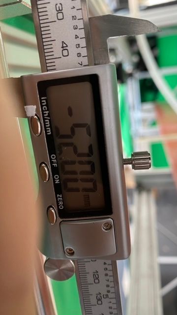
                                  I am trying to work out how to calculate the steps per mm if 2000 s/mm is giving me 52mm translation when I send 50. I can't seem to work out how to work it out embarrassingly

                                  1 Reply Last reply Reply Quote 0
                                  • Charles Fraserundefined
                                    Charles Fraser @T3P3Tony
                                    last edited by Charles Fraser

                                    @t3p3tony

                                    M92 X80.00 Y1280.00 Z1926.78 E420.00          ; set steps per mm
                                    

                                    okay this seems to be near enough

                                    If I divide 100,000 steps by 52mm I get
                                    1926.78 s/mm if

                                    When I use value z1926.00 I get the following on a 50mm command

                                    8A54FC36-B003-42A5-9482-72A643DFB436.jpeg

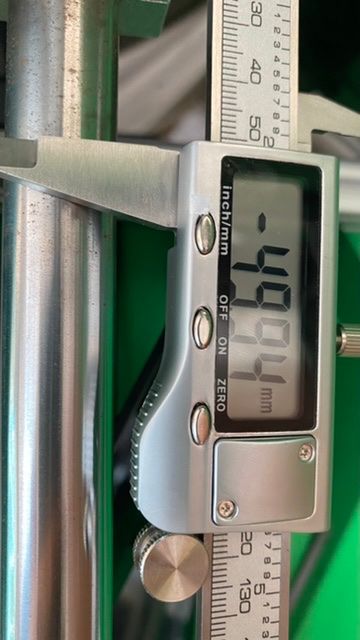
                                    If I divide 51.9 mm by 100,000 steps I get 1926.78
                                    That translates to

                                    5827BCA8-4738-4017-A92E-66888A6EF31A.jpeg

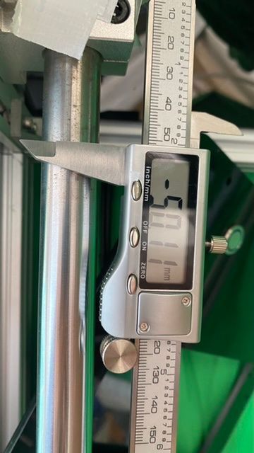
                                    They are both .1 of a mm out. Is that okay if I am printing big things. No not really it needs to be less.

                                    So I go between those two z1926.39

                                    1 Reply Last reply Reply Quote 0
                                    • Charles Fraserundefined
                                      Charles Fraser @T3P3Tony
                                      last edited by Charles Fraser

                                      @t3p3tony iwhen I hit home all the z axis goes the wrong way

                                      In fact, when I hit any of the home buttons, all it does is send the z axis the wrong way

                                      T3P3Tonyundefined 1 Reply Last reply Reply Quote 0
                                      • T3P3Tonyundefined
                                        T3P3Tony administrators @Charles Fraser
                                        last edited by

                                        @charles-fraser for Z when you jog it using DWC by a few mm does it move in the expected direction?

                                        For the steps/mm this is really not something you measure for XYZ it something to calculate.

                                        So
                                        lead = 5mm
                                        motor microsteps/rev = 3200 (with 16 microstepping and 1.8 degree motors it would be 3200)
                                        the unknown to me is the ratio between the pully teeth on the motor and the larger pully on the Z rods. how many teeth are on each?

                                        Once you know that we work out the steps/mm for Z.

                                        For the homing files, the first command is raise Z by 100mm (you can read the comments in the homing files).

                                        So looking at home X.

                                        ; homex.g
                                        ; called to home the X axis
                                        ;
                                        ; generated by RepRapFirmware Configuration Tool v3.3.3 on Fri Oct 01 2021 16:59:55 GMT+0100 (British Summer Time)
                                        G91                ; relative positioning
                                        G1 H2 Z100 F6000   ; lift Z relative to current position
                                        G1 H1 X-1205 F1800 ; move quickly to X axis endstop and stop there (first pass)
                                        G1 H2 X5 F6000     ; go back a few mm
                                        G1 H1 X-1205 F360  ; move slowly to X axis endstop once more (second pass)
                                        G1 H2 Z-100 F6000  ; lower Z again
                                        G90                ; absolute positioning
                                        

                                        if you don't need to increase Z gap by 100 mm before homing then you can modify that line to a more appropriate amount. (but be sure to change the value on line 10 to match!)

                                        Then the file moves X in a negative direction (which is correct assuming the end stop is at X minimum)

                                        once its triggered it backs off and then tests again slower

                                        then it decreases the Z gap (again this should match the amount in line 6).

                                        Similar with the Home Y

                                        Home all just puts it together into a fewer steps and then homes Z however as it stands that home all wont work correctly as its setup for a Z probe.

                                        You mentioned you added a Z switch, where is it located (Z min or Z max?)

                                        www.duet3d.com

                                        Charles Fraserundefined 1 Reply Last reply Reply Quote 0
                                        • Charles Fraserundefined
                                          Charles Fraser @T3P3Tony
                                          last edited by

                                          @t3p3tony

                                          Thanks Tony, I think I worked out the steps for Z

                                          The Z switch is triggered when the bed comes too close to the nozzle and pushes up against a switch. I’m not sure if that is min or Max?

                                          Charles Fraserundefined T3P3Tonyundefined 2 Replies Last reply Reply Quote 0
                                          • Charles Fraserundefined
                                            Charles Fraser @Charles Fraser
                                            last edited by

                                            @charles-fraser

                                            ya so I swapped the z probe for a z switch for now but think we can reattach the 3d touch to the other extruder block and set that up now too if you are game? Is there a way to speed up the fast z movement please? It's now much slower than it was before. Now all the switches are open for all axis.

                                            ; Endstops
                                            M574 X1 S1 P"io1.in"                                            ; configure active-high endstop for low end on X via pin io1.in
                                            M574 Y1 S1 P"io2.in"                                            ; configure active-high endstop for low end on Y via pin io2.in
                                            M574 Z1 S1 P"io0.in"   
                                            
                                            1 Reply Last reply Reply Quote 0
                                            • First post
                                              Last post
                                            Unless otherwise noted, all forum content is licensed under CC-BY-SA