Firmware for hotend of dual extruder head
-
Configuring Gcode for a dual extruder head on duet mainboard 6hc and extension board 3HC. I have the following wiring for the dual extruder head (two direct extruders side-by side). But I have not made any further progress.
Primary extruder heater --> expansion board out1
Primary extruder thermistor --> expansion board temp1
Primary extruder fan --> expansion board out 7
Primary extruder --> expansion board driver1Secondary extruder heater --> expansion board out2
Secondary extruder thermistor --> expansion board temp2
Secondary extruder fan --> expansion board out 8
Secondary extruder --> expansion board driver2My best guess on how the Gcode would look based on the config tool would be something similar to the code below. But it isn't taking into account the fact that the connections are being made on the extension board not the mainboard. So that I know it is wrong also there is only one tool defined. I am thinking there would probably need to be two defined.
; Heaters M308 S0 P"temp1" Y"thermistor" T100000 B4138 ; configure sensor 0 as thermistor on pin temp1 M950 H0 C"out1" T0 ; create nozzle heater output on out1 and map it to sensor 0 M307 H0 B0 S1.00 ; disable bang-bang mode for heater and set PWM limit M143 H0 S280 ; set temperature limit for heater 0 to 280C M308 S1 P"temp2" Y"thermistor" T100000 B4138 ; configure sensor 1 as thermistor on pin temp2 M950 H1 C"out2" T1 ; create nozzle heater output on out2 and map it to sensor 1 M307 H1 B0 S1.00 ; disable bang-bang mode for heater and set PWM limit M143 H1 S280 ; set temperature limit for heater 1 to 280C ; Fans M950 F0 C"out7" Q500 ; create fan 0 on pin out7 and set its frequency M106 P0 S1 H-1 ; set fan 0 value. Thermostatic control is turned off M950 F1 C"out8" Q500 ; create fan 1 on pin out8 and set its frequency M106 P1 S1 H-1 ; set fan 1 value. Thermostatic control is turned off ; Tools M563 P0 D0 H1 F0 ; define tool 0 G10 P0 X0 Y0 Z0 ; set tool 0 axis offsets G10 P0 R0 S0 -
If the config tool generated this I don't think you clicked the button to add the expansion board on the i/o mapping page, or didn't select the expansion board entries in the dropdown menu.
For instance, here's what the config tool generates when you select the 3HC expansion and use it's ports.
; Heaters
M308 S0 P"1.temp0" Y"thermistor" T100000 B4138 ; configure sensor 0 as thermistor on pin 1.temp0
M950 H0 C"1.out0" T0                           ; create bed heater output on 1.out0 and map it to sensor 0
M307 H0 B1 S1.00                               ; enable bang-bang mode for the bed heater and set PWM limit
M140 H0                                        ; map heated bed to heater 0
M143 H0 S120                                   ; set temperature limit for heater 0 to 120C
M308 S1 P"1.temp1" Y"thermistor" T100000 B4138 ; configure sensor 1 as thermistor on pin 1.temp1
M950 H1 C"1.out1" T1                           ; create nozzle heater output on 1.out1 and map it to sensor 1
M307 H1 B0 S1.00                               ; disable bang-bang mode for heater  and set PWM limit
M143 H1 S280                                   ; set temperature limit for heater 1 to 280C

; Fans
M950 F0 C"1.out3" Q500                         ; create fan 0 on pin 1.out3 and set its frequency
M106 P0 S0 H-1                                 ; set fan 0 value. Thermostatic control is turned off
M950 F1 C"1.out4" Q500                         ; create fan 1 on pin 1.out4 and set its frequency
M106 P1 S1 H1 T45                              ; set fan 1 value. Thermostatic control is turned on
Note the leeding 1. on the pin names which denotes it's the 1st expansion board. 0. would indicate the mainboard, or if no expansions are present, no leading digit can be used at all as it assumes its on the mainboard.
-
@feynman137 In addition to what @Phaedrux has said, you also need to use the board prefix when setting the drive mapping using M569. For example, if the first extruder motor was connected to expansion board1 driver 0, then the M569 command would be M569 P1.0 Sn.
Yes, you need to define 2 tools so for example M563 P0 D0 Hn Fn and M563 P1 D1 Hn Fn.
Note also that when defining tools, the drive number (D) refers to the extruder drive as defined in M584, and not the physical drive. So your M584 might end E1.0:1.1 if the extruder motors were connected to drives 0 and 1 of expansion board 1. In that case, using M563, D0 will refer to physical drive 1.0 (expansion board 1, driver 0) and D1 will refer to physical drive 1.1 (expansion board 1 driver 1).
-
@deckingman thank you very much for this info. Especially the M584 comment, I had this all messed up. And in my head I was wondering how the code was tying heater to its respective extrusion drive. So this comment answers this question for me, it is in the tool definition. @Phaedrux thank you for the guidance you were correct I had not added the expansion board in the config tool. After doing this I was able to see the format that you displayed in your answer. I am posting my updated config.g file below.
; Configuration file for Duet 3 (firmware version 3) ; executed by the firmware on start-up ; ; generated by RepRapFirmware Configuration Tool v3.2.3 on Wed Jun 23 2021 23:47:21 GMT-0400 (Eastern Daylight Time) ; General preferences G90 ; send absolute coordinates... M83 ; ...but relative extruder moves M550 P"Duet 3" ; set printer name M669 K1 ; select CoreXY mode ; Drives M569 P0.0 S1 ; physical drive 0.0 goes forwards M569 P0.1 S1 ; physical drive 0.1 goes forwards M569 P0.2 S1 ; physical drive 0.2 goes forwards M569 P0.3 S1 ; physical drive 0.3 goes forwards M569 P0.4 S1 ; physical drive 0.4 goes forwards M569 P0.5 S1 ; physical drive 0.5 goes forwards M569 P1.1 S1 ; physical drive 1.1 goes forwards M569 P1.2 S1 ; physical drive 1.2 goes forwards M584 X0.0 Y0.1 Z0.2:0.3:0.4:0.5 E1.1:1.2 ; set drive mapping M350 X16 Y16 Z16 E16:16 I1 ; configure microstepping with interpolation M92 X40.00 Y40.00 Z400.00 E420.00:420.00 ; set steps per mm M566 X900.00 Y900.00 Z60.00 E120.00:120.00 ; set maximum instantaneous speed changes (mm/min) M203 X6000.00 Y6000.00 Z120.00 E1200.00:1200.00 ; set maximum speeds (mm/min) M201 X500.00 Y500.00 Z10.00 E250.00:250.00 ; set accelerations (mm/s^2) M906 X1500 Y1500 Z1500 E800:800 I30 ; set motor currents (mA) and motor idle factor in per cent M84 S30 ; Set idle timeout ; Axis Limits M208 X0 Y0 Z0 S1 ; set axis minima M208 X600 Y540 Z496 S0 ; set axis maxima ; Endstops M574 X1 S1 P"!io4.in" ; configure active-low endstop for low end on X via pin !io1.in M574 Y1 S1 P"!io5.in" ; configure active-low endstop for low end on Y via pin !io5.in M574 Z2 S1 P"!io3.in" ; configure active-low endstop for low end on Z via pin !io3.in ; Z-Probe M950 S0 C"io7.out" ; create servo pin 0 for BLTouch M558 P9 C"^io7.in" H7 F120 T6000 ; set Z probe type to bltouch and the dive height + speeds G31 P500 X0 Y0 Z1.67 ; set Z probe trigger value, offset and trigger height M557 X10:600 Y10:540 S100 ; define mesh grid ; Heaters M308 S0 P"1.temp0" Y"thermistor" T100000 B4138 ; configure sensor 0 as thermistor on expansion board pin 1.temp0 M950 H0 C"1.out0" T0 ; create nozzle heater output on 1.out0 and map it to sensor 0 M307 H0 B0 S1.00 ; disable bang-bang mode for heater and set PWM limit M143 H0 S280 ; set temperature limit for heater 0 to 280C M308 S1 P"1.temp1" Y"thermistor" T100000 B4138 ; configure sensor 2 as thermistor on expansion board pin 1.temp1 M950 H1 C"1.out1" T1 ; create nozzle heater output on 1.out2 and map it to sensor 1 M307 H1 B0 S1.00 ; disable bang-bang mode for heater and set PWM limit M143 H1 S280 ; set temperature limit for heater 1 to 280C ; bed heater0 M308 S2 P"0.temp0" Y"thermistor" T100000 B4138 ; configure sensor 2 as thermistor on mainboard pin temp0 M950 H2 C"0.out9" T2 ; create bed heater output on 1.out0 and map it to sensor 2 M140 P0 H2 ;assign H2 to bed heater0 M307 H2 B0 S10.00 ; disable bang-bang mode for the bed heater and set PWM limit M143 H2 S120 ;set temperature limit for heater 0 to 120C ; bed heater1 M308 S3 P"0.temp1" Y"thermistor" T100000 B4138 ; configure sensor 3 as thermistor on mainboard pin temp1 M950 H3 C"0.out6" T3 ; create bed heater output on 1.out0 and map it to sensor 3 M140 P1 H3 ;assign H2 to bed heater0 M307 H3 B0 S10.00 ; disable bang-bang mode for the bed heater and set PWM limit M143 H3 S120 ;set temperature limit for heater 0 to 120C ; bed heater2 M308 S4 P"0.temp2" Y"thermistor" T100000 B4138 ; configure sensor 4 as thermistor on mainboard pin temp2 M950 H4 C"0.out5" T4 ; create bed heater output on 1.out0 and map it to sensor 4 M140 P2 H4 ;assign H2 to bed heater0 M307 H4 B0 S10.00 ; disable bang-bang mode for the bed heater and set PWM limit M143 H4 S120 ;set temperature limit for heater 0 to 120C ; bed heater3 M308 S5 P"0.temp3" Y"thermistor" T100000 B4138 ; configure sensor 5 as thermistor on mainboard pin temp3 M950 H5 C"0.out4" T5 ; create bed heater output on 1.out0 and map it to sensor 5 M140 P3 H5 ;assign H2 to bed heater0 M307 H5 B0 S10.00 ; disable bang-bang mode for the bed heater and set PWM limit M143 H5 S120 ;set temperature limit for heater 0 to 120C ; Fans M950 F0 C"1.out7" Q500 ; create fan 0 on pin 1.out7 and set its frequency M106 P0 S0 H-1 ; set fan 0 value. Thermostatic control is turned off M950 F1 C"1.out8" Q500 ; create fan 1 on pin 1.out8 and set its frequency M106 P1 S1 H-1 ; set fan 1 value. Thermostatic control is turned off ; Tools M563 P0 D0 H0 F0 ; define tool 0 G10 P0 X23.9 Y-28.21 Z0 ; set tool 0 axis offsets G10 P0 R0 S0 ; set initial tool 0 active and standby temperatures to 0C M563 P1 D1 H1 F1 ; define tool 1 G10 P1 X-23.9 Y-28.21 Z0 ; set tool 1 axis offsets G10 P1 R0 S0 ; set initial tool 0 active and standby temperatures to 0C ; Custom settings are not defined ; Miscellaneous M575 P1 S1 B57600 ; enable support for PanelDue -
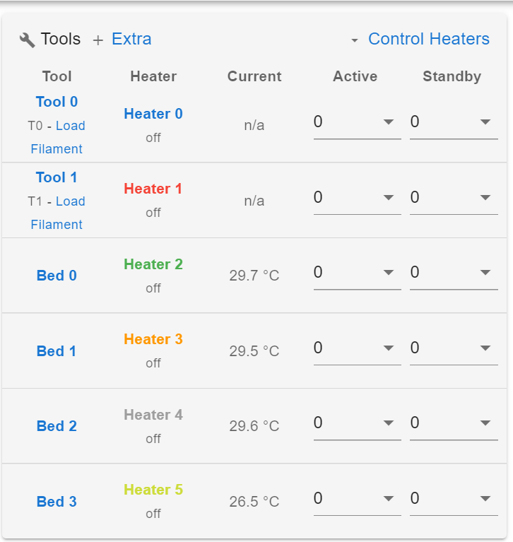
@feynman137 I corrected my existing code but for some reason the tool0 and tool1 don't have the temperature reading.
-
; Tools
M563 P0 D1.1 H0 F0 ; define tool 0
G10 P0 X23.9 Y-28.21 Z0 ; set tool 0 axis offsets
G10 P0 R0 S0 ; set initial tool 0 active and standby temperatures to 0C
M563 P1 D1.2 H1 F1 ; define tool 1
G10 P1 X-23.9 Y-28.21 Z0 ; set tool 1 axis offsets
G10 P1 R0 S0 ; set initial tool 0 active and standby temperatures to 0CYou didn't change the D values as I had mentioned earlier. It's probably ignoring everything after that.
Also, don't forget you can check for syntax errors with M98 P"config.g"
-
@phaedrux I did change the D values as suggested before I tried. But I have updated the code in the message thread to reflect this. Now the tool portion looks like:
; Tools
M563 P0 D0 H0 F0                                ; define tool 0
G10 P0 X23.9 Y-28.21 Z0                          ; set tool 0 axis offsets
G10 P0 R0 S0                                    ; set initial tool 0 active and standby temperatures to 0C
M563 P1 D1 H1 F1                                ; define tool 1
G10 P1 X-23.9 Y-28.21 Z0                         ; set tool 1 axis offsets
G10 P1 R0 S0                                    ; set initial tool 0 active and standby temperatures to 0C
M98 P"config.g" gives:
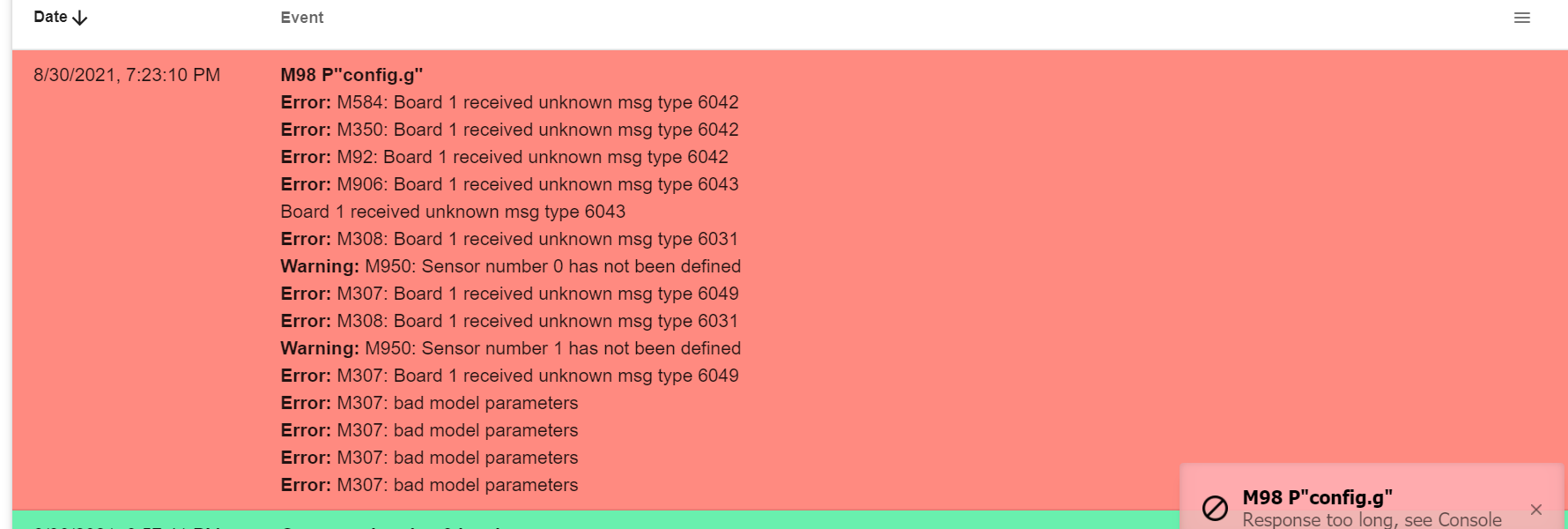
It seems to be saying that S0 and S1 are not defined. But they are defined in my code here:
; Heaters M308 S0 P"1.temp0" Y"thermistor" T100000 B4138 ; configure sensor 0 as thermistor on expansion board pin 1.temp0 M950 H0 C"1.out0" T0 ; create nozzle heater output on 1.out0 and map it to sensor 0 M307 H0 B0 S1.00 ; disable bang-bang mode for heater and set PWM limit M143 H0 S280 ; set temperature limit for heater 0 to 280C M308 S1 P"1.temp1" Y"thermistor" T100000 B4138 ; configure sensor 2 as thermistor on expansion board pin 1.temp1 M950 H1 C"1.out1" T1 ; create nozzle heater output on 1.out2 and map it to sensor 1 M307 H1 B0 S1.00 ; disable bang-bang mode for heater and set PWM limit M143 H1 S280 ; set temperature limit for heater 1 to 280C -
@feynman137 also wanted to add that if I switch the bed heaters to reading a thermistor from the expansion board instead of the mainboard I will no longer be able to get their temperature either. So the errors must be related to the expansion board. I can get the H0 to display a temperature if I list a mainboard thermistor so it likely isn't something related to the H0 config
-
Can you post the results of sending M122 and M122 B1 please?
-
@phaedrux said in Firmware for hotend of dual extruder head:
M122
M122
M122
=== Diagnostics ===
RepRapFirmware for Duet 3 MB6HC version 3.3 (2021-06-15 21:45:47) running on Duet 3 MB6HC v1.01 or later (SBC mode)
Board ID: 08DJM-956L2-G43S8-6J9DJ-3SJ6N-980QG
Used output buffers: 1 of 40 (13 max)
=== RTOS ===
Static ram: 150904
Dynamic ram: 62680 of which 88 recycled
Never used RAM 140520, free system stack 200 words
Tasks: SBC(ready,5.3%,328) HEAT(delaying,0.0%,325) Move(notifyWait,0.0%,352) CanReceiv(notifyWait,0.0%,799) CanSender(notifyWait,0.0%,374) CanClock(delaying,0.0%,339) TMC(notifyWait,7.1%,93) MAIN(running,87.5%,922) IDLE(ready,0.0%,29), total 100.0%
Owned mutexes: HTTP(MAIN)
=== Platform ===
Last reset 00:04:48 ago, cause: power up
Last software reset at 2021-08-30 20:54, reason: User, none spinning, available RAM 140812, slot 0
Software reset code 0x0012 HFSR 0x00000000 CFSR 0x00000000 ICSR 0x0044a000 BFAR 0x00000000 SP 0x00000000 Task SBC Freestk 0 n/a
Error status: 0x00
Aux0 errors 0,0,0
Step timer max interval 182
MCU temperature: min 29.3, current 43.8, max 43.9
Supply voltage: min 23.7, current 23.7, max 23.8, under voltage events: 0, over voltage events: 0, power good: yes
12V rail voltage: min 11.9, current 12.0, max 12.0, under voltage events: 0
Heap OK, handles allocated/used 0/0, heap memory allocated/used/recyclable 0/0/0, gc cycles 0
Driver 0: position 0, standstill, reads 35775, writes 14 timeouts 0, SG min/max 0/0
Driver 1: position 0, standstill, reads 35776, writes 14 timeouts 0, SG min/max 0/0
Driver 2: position 0, standstill, reads 35776, writes 14 timeouts 0, SG min/max 0/0
Driver 3: position 0, standstill, reads 35776, writes 14 timeouts 0, SG min/max 0/0
Driver 4: position 0, standstill, reads 35776, writes 14 timeouts 0, SG min/max 0/0
Driver 5: position 0, standstill, reads 35776, writes 14 timeouts 0, SG min/max 0/0
Date/time: 2021-08-31 18:07:31
Slowest loop: 0.45ms; fastest: 0.04ms
=== Storage ===
Free file entries: 10
SD card 0 not detected, interface speed: 37.5MBytes/sec
SD card longest read time 0.0ms, write time 0.0ms, max retries 0
=== Move ===
DMs created 125, maxWait 0ms, bed compensation in use: none, comp offset 0.000
=== MainDDARing ===
Scheduled moves 0, completed moves 0, hiccups 0, stepErrors 0, LaErrors 0, Underruns [0, 0, 0], CDDA state -1
=== AuxDDARing ===
Scheduled moves 0, completed moves 0, hiccups 0, stepErrors 0, LaErrors 0, Underruns [0, 0, 0], CDDA state -1
=== Heat ===
Bed heaters = 2 3 4 5 -1 -1 -1 -1 -1 -1 -1 -1, chamberHeaters = -1 -1 -1 -1
=== GCodes ===
Segments left: 0
Movement lock held by null
HTTP* is doing "M122" in state(s) 0
Telnet is idle in state(s) 0
File is idle in state(s) 0
USB is idle in state(s) 0
Aux is idle in state(s) 0
Trigger* is idle in state(s) 0
Queue is idle in state(s) 0
LCD is idle in state(s) 0
SBC is idle in state(s) 0
Daemon is idle in state(s) 0
Aux2 is idle in state(s) 0
Autopause is idle in state(s) 0
Code queue is empty.
=== CAN ===
Messages queued 2509, received 2110, lost 0, longest wait 2ms for reply type 6049, peak Tx sync delay 248, free buffers 49 (min 48), ts 1442/1441/0
Tx timeouts 0,0,0,0,0,0
=== SBC interface ===
State: 4, failed transfers: 1, checksum errors: 0
Last transfer: 1ms ago
RX/TX seq numbers: 9187/9187
SPI underruns 0, overruns 0
Disconnects: 0, timeouts: 0, IAP RAM available 0x2c818
Buffer RX/TX: 0/0-0
=== Duet Control Server ===
Duet Control Server v3.3.0
Code buffer space: 4096
Configured SPI speed: 8000000Hz
Full transfers per second: 0.14, max wait times: 13.0ms/0.0ms
Codes per second: 0.00
Maximum length of RX/TX data transfers: 3159/836
M122 B1
M122 B1 Diagnostics for board 1: Board EXP3HC firmware 3.1.0 (2020-05-15b1) Never used RAM 163.1Kb, max stack 320b HEAT 1072 CanAsync 1452 CanRecv 1388 TMC 156 AIN 524 MAIN 2184 Last reset 00:06:12 ago, cause: power up Driver 0: standstill, reads 64061, writes 11 timeouts 0, SG min/max 0/0 Driver 1: standstill, reads 64063, writes 11 timeouts 0, SG min/max 0/0 Driver 2: standstill, reads 64065, writes 11 timeouts 0, SG min/max 0/0 Moves scheduled 0, completed 0, hiccups 0 VIN: 24.0V, V12: 12.2V MCU temperature: min 43.6C, current 43.8C, max 43.8C Ticks since heat task active 42, ADC conversions started 372036, completed 372036, timed out 0 Last sensors broadcast 00000000 found 0 45 ticks ago Free CAN buffers: 36 NVM user row de9a9239 aeecffb1 ffffffff ffffffff -
So the mainboard does appear to be connecting to the expansion board.
-
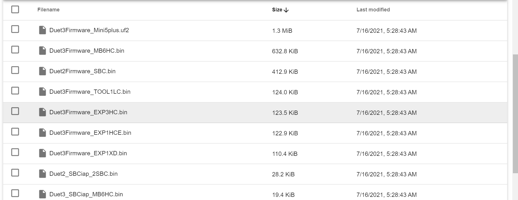
The expansion board is running older firmware than the mainboard. You need to update it. If you've already uploaded the 3.3 zip file to the system tab in DWC, all you need to do is send M997 B1 to flash the expansion.
https://github.com/Duet3D/RepRapFirmware/releases/download/3.3/Duet2and3Firmware-3.3.zip
-
Actually I also see that you are using SBC mode. Have you done a sudo apt update sudo apt upgrade lately?
-
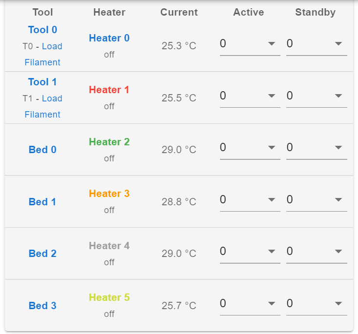
@phaedrux I did this last month I remember. But I don't think I flashed it to the expansion board. Because I ran the M997 B1 and reset the board. Now I can see all 6 temperatures!
-
Occasionally the expansion boards don't get updated automatically. I think that is being improved upon.
Regardless, it's also a good idea to check the installed firmware versions after an update with M115 and M115 B# for the expansion boards.
I would suggest that you do a sudo apt update and sudo apt upgrade again just in case. Ideally you'd only have to do that once for each major release going forward.