Self Leveling (3 motor leadscrew) printer = Non-planar printer?
-
@roiki11 said in Self Leveling (3 motor leadscrew) printer = Non-planar printer?:
Linuxcnc actually has that, has had for years. It’s just not very usable in a machining context and there’s no slicer to try it with a 3d printer.
I'll think about what you wrote.
But I don't understand the sentence above about LinuxCNC. From my understanding, LinuxCNC has G-Code as input, so it's already behind the slicer. This G-Code should be usable by RRF also (maybe some incompatible commands need to be changed by a postprocessor).
-
Linuxcnc is a machine controller, like duet and RRF. The G-code is largely the same, aside from some codes that might be specific to machining or 3D printing. If you had a slicer that would output a 5 axis G-code with the standard tool vector co-ordinates, you could build a 5 axis printer with linuxcnc. Though it’s missing the more advanced 3D printing focused features.
-
Here is better drawing

I'm not yet sure how to solve as I haven't done much match with vectors.
Main printer: 3-5 Axis, 400x400x450 Duet 6HC || https://grabcad.com/eetu-4/models
-
This post is deleted! -
It will be good to add coordinates to the edges A B C, i. e. which xy coordinates the edges of the D4, D5, D6 have. Do you have this information? Then I'll help with vector calculation.
I guess the edges are about A (0,0), B (200,-50) C (150,-200).
Those XY coordinates are not the coordinates of the 3 axes, but of the tilted plane.
-
Which place would you set as origin?
I added coordinates of each line end points (these are just given example value solutions) to the drawing above (D4 as middle point as origin).Main printer: 3-5 Axis, 400x400x450 Duet 6HC || https://grabcad.com/eetu-4/models
-
This post is deleted! -
This post is deleted! -
@Visionary
ok, this calculation was also wrong. I'll try again... Unfortunately I used a wrong formula.If you could add the vector coordinates, this would be good. Maybe vector calculation is easiest.
-
@joergs5
Ok, I updated the drawing again. I don't know why but I do also get wrong solutions for example if I try to solve system of three equations: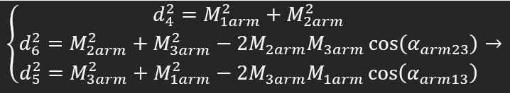
Main printer: 3-5 Axis, 400x400x450 Duet 6HC || https://grabcad.com/eetu-4/models
-
@visionary said in Self Leveling (3 motor leadscrew) printer = Non-planar printer?:
wrong solutions for example if I t
the formula is correct, maybe you calculated cos wrong, most calculation programs expect rad instead of degrees.
I verified the third formula, it's ok at me. arm13 being 135 degree and in calc I use the formula ...* COS(PI() / 180 * E6), E6 being degrees. -
@visionary my current approach is:
combine the first solution proposal of:
https://math.stackexchange.com/questions/3342547/curve-for-constant-angle-for-two-fixed-points
which calculated the curve which M1 M3 takes with the angle 135 degreewith the crossing the halfe curve around the midpoint. Both have two variables xy, so it should be solvable. Unfortunately the first formula uses specific coordinates, and it's difficult to understand how to generalize for arbitrary coordinates.
-
@roiki11
As it seems, there are several ways to build a non-planar printer, but would they all be happy with one slicer solution?
E.g.: rotating head vs. tilting bed.
The slicer would dictate how extra printer axes have to be named (eg. A/B), which wouldn't work for all.
IMHO, there has to be a new printer class first and it's requirements dictate the slicer-code.If Prusa decided to develop a non-planar printer, they would also come up with a dedicated slicer. But the benefits of this new type are marginal vs. the effort to make it happen.
-
@visionary I've rotated your triangle now, so D5 is horizontal on top (so I can calculate by the restricted formula of the link I provided), then calculated the midpoint and have xy with two equations. As mathematicians like to say, the rest is trivial.
") , not really.
, not really.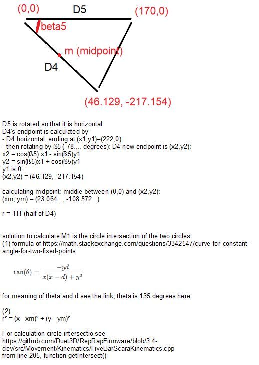
The first formula has an interesting symmetry:
x² + y² = (x + y) dsymmetry doesn't help, as it is the mirroring at the diagonal x=y, and the crossing with the other formula is the low red segment:
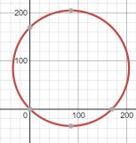
(created with online Desmos)
The midpoint is (85,85) and radius is sqrt of 85²+85²= about 120.208
-
Not true. In CNC world the 5 axis programs are supplied as tool vector coordinates (X, Y, Z for the tip, I, J, K for the vectot point) and it's the machine itself that applies the appropriate transformations to run the machine. The CAM software doesn't need any machine specific information to create the code, though specific limitations of individual machines are not taken into account(there's Sim software for that).
The same approach would have to be done on th slicer in order to not lock it for a specific machine configuration that it's designed for. You're right about that.
-
Have you though about looking at Stewart platform kinematics? It's a pretty similar in concept, it just has more movable axes.
-
Sorry but I have hard time trying understand your handwriting. Which of the angles is theta?
Main printer: 3-5 Axis, 400x400x450 Duet 6HC || https://grabcad.com/eetu-4/models
-
@visionary said in Self Leveling (3 motor leadscrew) printer = Non-planar printer?:
Which of the angles is theta?
theta is the 135 degree angle and is the angle being used in the article https://math.stackexchange.com/questions/3342547/curve-for-constant-angle-for-two-fixed-points at the B point, in the first answer angle ABC.
I know I have an awful handwriting, sorry for that!
-
@roiki11 said in Self Leveling (3 motor leadscrew) printer = Non-planar printer?:
Have you though about looking at Stewart platform kinematics?
I am not the creator of this thread, so it's better to ask @Visionary . I personally know the stewart/hexapod platform and it's interesting. There has been other users trying to implement in RRF already, like in https://forum.duet3d.com/topic/7635/custom-kinematics-on-duet/14 but I think it was not finished, as so many projects.
-
The main reason why kinematics that is explained in this threads might be better than Stewart platform or any traditional way do +5 axes I've seen is that is easy to do mechanically with off the self parts. Machines like it already exist (for example Arnold_R_Clark's machine in this thread), but they still lack kinematics in software for Duet. Stewart machine relies on actuators that are hard to built or are expensive. This thread's kinematics can be used with linear rails or linear rods (though they can be expensive too).
Other pros:
- This bed system that has rotational axes does not have X-and Y-axes. This means X-and Y-axes can have any setup there is (idex, toolchanger,...).
- The system can be used normally with 2,5D slicers and do high quality prints. I assume that some setups for +5 Axes are heavy X/Y-gantries plagued by rigidity and positional accuracy problems (if compared something like Prusa or Voron print quality).
- With Duet 3 6HC no extra boards are needed.
- I happen to have many of the parts for this build.
- Unlike most printer designs, the design I'm aiming for is something that does not have printed parts or machined special parts. Simple plate 5mm aluminum plate parts are super easy to manufacture
Main printer: 3-5 Axis, 400x400x450 Duet 6HC || https://grabcad.com/eetu-4/models