Are these accelerometer measurements reasonable?
-
I connected a LIS3DSH accelerometer to a Mini5+ (using a 330ohms data output serial resistor, and a ~1.5m 7 cores 28AWG cable), initialized it using the config.g command:
M955 P0 C"io3.out+io3.in"Then run the command:
G1 X-50 G4 S2 G1 X50 F20000 M400 M956 P0 S1000 A0The results I get, with the accelerometer stationary (not attached mechanically to the printer) are below. Are they reasonable? I would expect much smother plots.
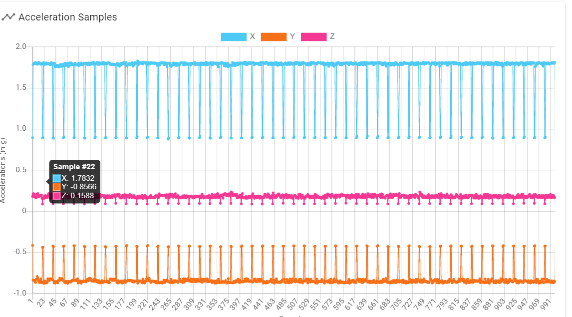
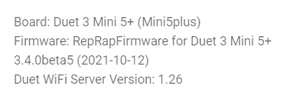
I am using this version
-
@zapta those readings don't look right. Is there a message at the end of the .csv file? Is the accelerometer clear of other wiring?
-
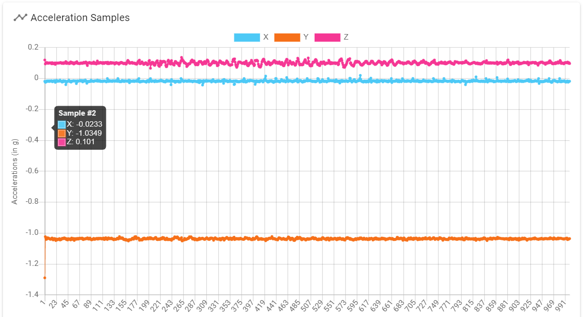
@dc42 , the cable didn't run near other cables. I tried again with another accelerometer board (same model), shorter and loose wires and no serial resistors and got the data below which looks reasonable, so it was probably a noise issue. I will experiment with it more, see if I can make it to work.
My cable of choice is ~1.5m of the 7 wires version of this https://tensility.s3.amazonaws.com/uploads/pdffiles/30-01171.pdf
-
Do you think it should work?
-
What should I do with the cable shield? When I got the noise it was floating on both sides. Does it matter?
-
The text says 100 - 1000 ohms resistors so I used 330. Should I experiment with it as well?
Edit: just ordered a ribbon cable. Should arrive tomorrow. It may have better characteristics for this application.
-
-
@zapta A few people (myself included) have had success using a USB3 cable, see: https://forum.duet3d.com/topic/22878/software-package-3-3beta3-released/68?_=1624809172098
-
Thanks @gloomyandy, I will give it a try. I have a couple of questions though
- What duet board are you using?
- What is the length of the cable you are using?
- Did you add a serial resistor on MISO?
- I couldn't find on Amazon US the exact extender cable you suggested, do you think that most USB3 extender would work?
Thanks.
-
@zapta Hi, I'm actually using an STM32 based board not a Duet, but I know of a few folks that have used a similar USB3 cable with Duets. My cable is just under 1 metre but I think @jay_s_uk is using one that is 2.5m. I've not had to use any serial resistors with a LIS3DH. This is the cable I used https://www.amazon.co.uk/gp/product/B073LP3QP4, but the price on that seems to have gone up since I got mine. It's hard to be sure that what you are getting has all of the cable cores which is obviously important in this application.
-
@zapta I see you are using a LIS3DSH I've been doing a lot of testing with one of those and had problems getting it working reliably with the STM32 port of RRF. It seems the problem was ringing on the clock line and I found that adding a small (30pF) capacitor between clock and ground at the sensor board made it much better. This may be different with the Duet board and the cable you use, but it may be worth trying if you have problems and the resistors do not help.
-
Thanks @gloomyandy, I will follow your suggestions.
The STM32 MCU and board may have different electrical I/O characteristics to that of the Duet5+ but I will give it a try.
-
@zapta said in Are these accelerometer measurements reasonable?:
What should I do with the cable shield? When I got the noise it was floating on both sides. Does it matter?
It does matter. Connect the shield to ground at the Duet end.
-
 undefined gloomyandy referenced this topic
-
System referenced this topic