How to setup input shaping
-
I am trying to set up input shaping on my CoreXY machine (Voron 2.4 250mm). Per the instructions I connected a LIS3DSH accelerometer and run the measurement script below which generates two reports for X and for Y movements respectivly.
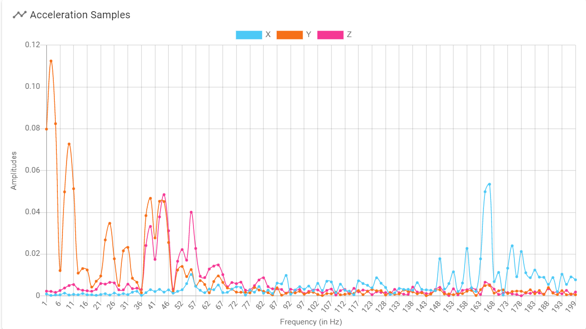
M593 P"none"

echo "Testing X"
G1 X75 Y125 Z50 G4 P2000 M956 P0 S1000 A0 G4 P10 G1 X225 F20000

echo "Delay 3 secs"
G4 P3000

echo "Testing Y"
G1 X125 Y75 Z50 G4 P2000 M956 P0 S1000 A0 G4 P10 G1 Y225 F20000
Which gave me two graphs, for the x movement and for the y movement respectively:
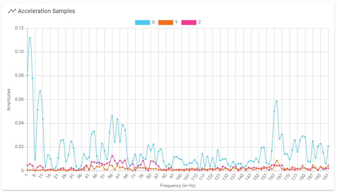
My understanding is that the next step for me is to set a command like this one where xxx is the algorithm code and yyy is the frequency in hertz.
M593 P"xxx" FyyyIs this correct so far? What algorithm code and what frequency should I set?
BTW, the measurement with movement in the Y direction seems to have more impact on the other two axis, is it expected? Something wrong in the way I measure it? (The accelerometer orientation is I50 if it matters).
-
Input shaping at this point is a guess and check system so you make a change, measure, make a change, measure, call it good.
Based upon your graphs I would start with a frequency of 46 hz. I would start with the EI3. This is working very well on my Voron 2.4 (350mm).
You have quite a few peaks, especially some out in the 160hz range. I never saw anything up that high on my machine. I would double check that your belts are tight. What is your printer sitting on for these measurements? Is it stable?
Here is are my settings for a similar machine to yours, just bigger.
M593 P"EI3" F54.0 -
@alex-cr, thanks, I will give it a try. I run an input shaping tower with "zvd" (an arbitrary choice) and best results were at 46Hz. I will try to do the same, fixing the frequency at 46Hz and varying the algorithm.
As for belt tension, I tried the recommended frequency app method (110hz for A/B, 140Hz for Z, over 150mm span) but am having difficulty getting consistent readings. Tried 3 different apps including the Gates iPhone app. Any suggestion on how to do that? In previous printers I used the deflection method with linear spring scale.
-
@zapta
I saw very little difference in the accelerometer results and printing quality between the different algorithms. That being said anything was better than not running them.I tensioned mine by feel. If you have gone that far I bet that is not a problem.
-
@alex-cr said in How to setup input shaping:
I saw very little difference in the accelerometer results and printing quality between the different algorithms.
I think this gives even more support to the idea of not getting bothered with setting up an accelerometer and just use that Kipper input shaping test model as an input shaping tower with varying resonance frequencies, since RRF allows to change it during printing (I don't know if Klipper can do that).
Just as we do for temp, retraction, and pressure advance calibrations
-
@zapta said in How to setup input shaping:
I think this gives even more support to the idea of not getting bothered with setting up an accelerometer and just use that Kipper input shaping test model as an input shaping tower with varying resonance frequencies, since RRF allows to change it during printing (I don't know if Klipper can do that).
https://duet3d.dozuki.com/Wiki/Pressure_advanceI only agree with that partly. I really like having the full visual feedback from the accelerometer and the FFT to establish the frequencies that need to be canceled. For instance your graphs above are really telling us you have multiple frequency's that are being excited. This type of direct measurement allows for more informed decisions overall.
That being said, people can forgo the accelerometer if they do not want to use it.