Strange delta calibration and mesh compensation
-
@t3p3tony
Yes it is.

but after I change the radius manually I get different results for M666 and M665 than before. And the values for the delta radius make no sense
-
@taconite please post your bed.g
And those before and after are very far apart. can you run it a few more times until they are almost identical.
-
Before:
M665 L414.000:414.000:414.000 R238 H464.288 B150.0 X-0.179 Y-0.582 Z0.000
M666 X-0.348 Y-0.068 Z0.417 A0.00 B0.00- Run
Calibrated 6 factors using 17 points, (mean, deviation) before (-0.957, 0.682) after (0.000, 0.177)
M665 L414.000:414.000:414.000 R233.065 H464.163 B150.0 X-0.099 Y-0.444 Z0.000
M666 X0.122 Y-0.165 Z0.043 A0.00 B0.00 - Run
Calibrated 6 factors using 17 points, (mean, deviation) before (0.399, 0.352) after (0.000, 0.105)
M665 L414.000:414.000:414.000 R235.823 H464.345 B150.0 X-0.067 Y-0.354 Z0.000
M666 X0.088 Y-0.270 Z0.182 A0.00 B0.00 - Run
Calibrated 6 factors using 17 points, (mean, deviation) before (-0.183, 0.231) after (0.000, 0.136)
M665 L414.000:414.000:414.000 R234.503 H464.243 B150.0 X-0.003 Y-0.529 Z0.000
M666 X0.236 Y-0.079 Z-0.157 A0.00 B0.00 - Run
Calibrated 6 factors using 17 points, (mean, deviation) before (0.085, 0.172) after (0.000, 0.090)
M665 L414.000:414.000:414.000 R235.252 H464.317 B150.0 X-0.176 Y-0.360 Z0.000
M666 X0.042 Y-0.337 Z0.295 A0.00 B0.00
; bed.g ; called to perform automatic delta calibration via G32 ; ; generated by RepRapFirmware Configuration Tool v2.1.8 on Fri Apr 10 2020 17:42:41 GMT+0200 (Mitteleuropäische Sommerzeit) M561 ; clear any bed transform G28 ; home all towers ; Probe the bed at 10 peripheral and 6 halfway points, and perform 6-factor auto compensation ; Before running this, you should have set up your Z-probe trigger height to suit your build, in the G31 command in config.g. G30 P0 X0 Y149.9 H0.107 Z-99999 G30 P1 X88.11 Y121.27 H0.447 Z-99999 G30 P2 X142.56 Y46.32 H0.532 Z-99999 G30 P3 X142.56 Y-46.32 H0.285 Z-99999 G30 P4 X88.11 Y-121.27 H0.130 Z-99999 G30 P5 X0 Y-149.9 H0.706 Z-99999 G30 P6 X-88.11 Y-121.27 H0.091 Z-99999 G30 P7 X-142.56 Y-46.32 H0.290 Z-99999 G30 P8 X-142.56 Y46.32 H0.350 Z-99999 G30 P9 X-88.11 Y121.27 H0.009 Z-99999 G30 P10 X0 Y74.9 H0.319 Z-99999 G30 P11 X64.87 Y37.45 H0.562 Z-99999 G30 P12 X64.87 Y-37.45 H0.450 Z-99999 G30 P13 X0 Y-74.9 H0.059 Z-99999 G30 P14 X-64.87 Y-37.45 H0.049 Z-99999 G30 P15 X-64.87 Y37.45 H0.085 Z-99999 G30 P16 X0 Y0 H0 Z-99999 S6 ; Use S-1 for measurements only, without calculations. Use S4 for endstop heights and Z-height only. Use S6 for full 6 factors ; If your Z probe has significantly different trigger heights depending on XY position, adjust the H parameters in the G30 commands accordingly. The value of each H parameter should be (trigger height at that XY position) - (trigger height at centre of bed) - Run
-
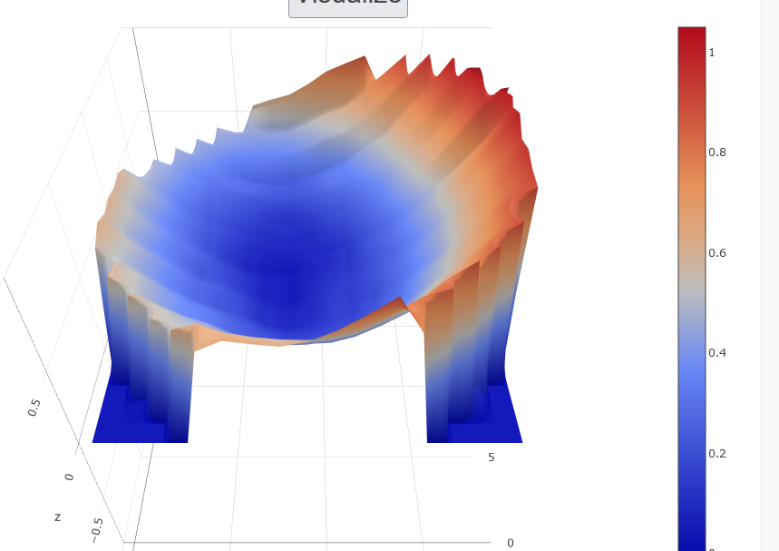
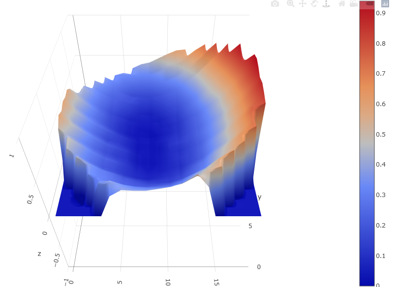
@T3P3Tony and if I do a mesh bed compensation with the last values it looks like this:

-
@taconite by the end its was getting there but still not fully converged, maybe try 8 runs, you don't need to send M665 and M666 between runs. I notice you have quite large H values in the G30 commands, did you measure all 17 of those accurately?
in 6 factor calibration the radius is adjusted as part of the calibration (note this is not the same as your bed radius) so manually adjusting it and then running G32 will cause G32 to be out for a few runs until it adjusts it back to what the calibration is measuring it as.
If after running G32 a number of times and then doing a mesh compensation you are still getting the bowl shape in mesh bed levelling then try temporarily dropping the number of points to 7 (6 in a ring around the outside of the bed, 3 in front of each tower and 3 roughly between the towers, and 1 in the center).
-
@t3p3tony
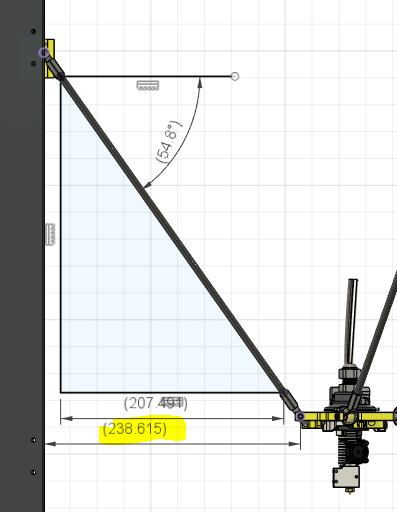
Okay. Yeah the M666 and M665 commands where just for reference. Yes I measured them with the section "Measuring the trigger height" in the wiki https://duet3d.dozuki.com/Wiki/Calibrating_a_delta_printer. Should I remove the H values?Yes as I understand the delta radius is this and as it is hard to measure in reality I took it from CAD.

Okay I will try some more runs and see what happens
-
@taconite said in Strange delta calibration and mesh compensation:
Should I remove the H values?
not if they are required. (i.e. if the probe trigger height relative to the nozzle varies across the bed.
-
so yeah nothing helped
- deleted the trigger heights from bed
- ran 13 cycles with 6-factor on 17 points
- ran 7 cycles with 7-factor on 17 points
Still the same result as the delta radius is adjusted
Any other ideas?
-
@t3p3tony said in Strange delta calibration and mesh compensation:
If after running G32 a number of times and then doing a mesh compensation you are still getting the bowl shape in mesh bed levelling then try temporarily dropping the number of points to 7 (6 in a ring around the outside of the bed, 3 in front of each tower and 3 roughly between the towers, and 1 in the center).
please try that.
-
yeah but what if the measured trigger height result in bad parameters from the beginning?
-
@taconite also, for now, the radius being adjusted is not necessarily wrong as maybe some element of the model you are using to determine the theoretical radius is off
-
@t3p3tony
Tried 7 iterations with just 7 pointsM665 L414.000:414.000:414.000 R235.772 H464.295 B150.0 X0.033 Y-0.455 Z0.000
M666 X0.028 Y-0.064 Z0.037 A0.00 B0.00deviation is a lot higher than with more points
Calibrated 6 factors using 7 points, (mean, deviation) before (-0.006, 0.235) after (-0.000, 0.235)before that it was more in this direction
Calibrated 6 factors using 17 points, (mean, deviation) before (0.000, 0.088) after (0.000, 0.088)
-
@taconite said in Strange delta calibration and mesh compensation:
Where are the images you are displaying coming from? I assumed you were plotting the heightmap.csv externally for some reason but now not so sure.
From the documentation you linked earlier it looks like your rod length could be a cause.
-
I use this page to view the mesh because I am getting the maximum deviation
http://lokspace.eu/3d-printer-auto-bed-leveling-mesh-visualizer/But 7 Factor was not working as well and I tried to manipulate it manually and it did not improve.
-
@taconite ahh i see. ok so try shortening the rod lengths with 6 factor and 7 probe points until you get a flatter bed shape.
-
@t3p3tony
Isn't that super tedious? In which intervals should I change the rod length? It should not be off by mm -
@taconite I suspect a problem with your Z probe and/or the joints of your printer. What type of Z probe are you using, and what sort of joints?
-
@dc42 thank you for your reply
Z-Probe: inductive sensor, M18, similar to what I was using on other printers
Joints: They are Ball-joints, Igus, KCRM-05 they have a little play which I compensated with springsEDIT: the nozzle is replaced by the sensor so it sits at X0 Y0
-
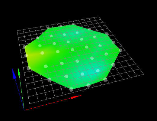
no it gets really strange. I decreased the size of the probing radius (calibration and mesh compensation) and with the "original" values I get this L414 R236
Calibrated 6 factors using 7 points, (mean, deviation) before (-0.000, 0.006) after (0.000, 0.005)
M665 L414.000:414.000:414.000 R238.041 H465.172 B150.0 X0.146 Y0.015 Z0.000
M666 X-0.003 Y-0.210 Z0.214 A0.00 B0.00
-
@taconite ahh ok so if you probe too close to the edge of the delta radius then that may cause issues, (the arms are almost straight down or straight out).
You are now getting much better results, and can see if you get much improvement with 17 points over 7. I have a slightly smaller bed on my delta and use 10 points (6 outer ring, 3 in an inner ring. 1 in the center).