Error:Invalid Remote Handle
-
New to the DUET ecosystem, Currently setting up a printer with Duet 3, Tool Expansion Board, 2 tool boards, 3 1xd boards and an mks tb6600 servo driver. X and Y have JSS57P2N motors and the z is driven by an mks tb6600. Having issues the motors connected properly and then setting up the correct codes to get them all running. Im also getting an error message of "Error":Invalid Remote Handle", what is that?
Any help is greatly appreciated
-
@thunderrunna error messages about remote handles typically occur if you reboot an expansion or tool board, or upgrade its firmware, or power it down and up again, and then you do not also reboot the main board.
If you are seeing these messages in other situations, then first you should run M122 B# where # is the CAN address of the expansion board concerned, to see if it has had an unexpected reset. Also check that the expansion boards are running the same firmware version as the main board.
Duet WiFi hardware designer and firmware engineer
Please do not ask me for Duet support via PM or email, use the forum
http://www.escher3d.com, https://miscsolutions.wordpress.com -
@dc42 thank you for the quick response. All the toolboards and mainboard had yheir firmwares updated yesterday so they are all running 3.3. Complete power down, to power up and the error occurs everytime. The boards are all independently powered via a 6 way hub from 1 power supply giving 24.3 volts. The motors (servo drivers which is another issue with the 1xd boards) are powered from their own power supply directly. Have changed the “delay” for can from 2 seconds upto 20 seconds with no change to this error occuring every time a complete shut down/power up is done.
-
@dc42 have also assigned each board with a new can address (20,21 for the 1lc tool boards abd 40,41,42 for the 1xd boards and all communications work as expected). Also, running the bondtech lgx flexible with the slice engineering hotends and the 300c thermistors, the thermistors read 78 degrees and fluctuate 0.5 degrees above and below. Is this simply an incorrect table value from the rep rap configurator?
-
@thunderrunna said in Error:Invalid Remote Handle:
have also assigned each board with a new can address (20,21 for the 1lc tool boards abd 40,41,42 for the 1xd boards and all communications work as expected)
Do you no longer get the errors on startup?
@thunderrunna said in Error:Invalid Remote Handle:
Also, running the bondtech lgx flexible with the slice engineering hotends and the 300c thermistors, the thermistors read 78 degrees and fluctuate 0.5 degrees above and below. Is this simply an incorrect table value from the rep rap configurator
Have a look in the M308 values in your config.g and compare them to the published values for those thermistors. 78C at room temp is not right.
https://duet3d.dozuki.com/Wiki/M308 -
@t3p3tony have tried a fresh sd card, re flash of firmwares to the main boards, checked communications before and after changing the board addresses and all communications work as expected.
The errors for the invalid remote handle still show on initial startup on the panel due and upon diagnostic request boththe duet 3 and toolboards show reset errors from power up.Have changed the thermistors as per the slice engineering tables and the temp readings only change1 degree.
-
 undefined T3P3Tony referenced this topic
-
undefined T3P3Tony referenced this topic
-
@thunderrunna with the multiple threads its hard to determine the sequence of what is going on here so i have locked the other threads and we can collect all the information here.
Please can you restart all the boards (including the main board). Then run M122 B# for each board and post the results here. When you post the results please place the result for each board in its own code block (use the </> button from the formatting tool bar) so that they can be viewed easily.
Also please post you full config.g in the same manner.
-
@t3p3tony config.g as follows, will get the board diagnosis read outs tomorrow when back at the printer
; Configuration file for Duet 3 (firmware version 3.3) ; executed by the firmware on start-up ; ; generated by RepRapFirmware Configuration Tool v3.3.5 on Sat Nov 20 2021 09:35:37 GMT+0800 (Australian Western Standard Time) ; General preferences M575 P1 S1 B57600 ; enable support for PanelDue G90 ; send absolute coordinates... M83 ; ...but relative extruder moves M550 P"Duet 3" ; set printer name ; Drives G4 S2 ; Wait for expansion boards to start M569 P40.0 S1 R1 T2.5:2.5:5:0 ; physical drive X 40.0.0 goes forwards, requires an active high enable M569 P41.0 S1 R1 T2.5:2.5:5:0 ; physical drive Y 40.0 goes forwards, requires an active high enable M569 P42.0 S0 R1 T2.5:2.5:5:0 ; physical drive Z 41.0 goes forwards, requires an active low enable M569 P20.0 S1 ; physical drive extruder 1 20.0 goes forwards M569 P21.0 S1 ; physical drive extruder 2 21.0 goes forwards M584 X40.0 Y41.0 Z42.0 E20.0:21.0 ; set drive mapping M350 X1 Y1 Z1 E16:16 I0 ; configure microstepping without interpolation M92 X6000.00 Y600.00 Z400.00 E420.00:420.00 ; set steps per mm M566 X900.00 Y900.00 Z60.00 E120.00:120.00 ; set maximum instantaneous speed changes (mm/min) M203 X6000.00 Y6000.00 Z180.00 E1200.00:1200.00 ; set maximum speeds (mm/min) M201 X500.00 Y500.00 Z20.00 E250.00:250.00 ; set accelerations (mm/s^2) M906 E600:600 I30 ; set motor currents (mA) and motor idle factor in per cent M84 S30 ; Set idle timeout ; Axis Limits M208 X0 Y0 Z0 S1 ; set axis minima M208 X600 Y600 Z600 S0 ; set axis maxima ; Endstops M574 X1 S1 P"20.io2.in" ; configure switch-type (e.g. microswitch) endstop for low end on X via pin 121.io2.in M574 Y1 S1 P"io1.in" ; configure switch-type (e.g. microswitch) endstop for low end on Y via pin io1.in ; Z-Probe M950 S0 C"20.io0.out" ; create servo pin 0 for BLTouch M558 P9 C"20.io0.in" H5 F120 T6000 ; set Z probe type to bltouch and the dive height + speeds G31 P500 X0 Y0 Z2.5 ; set Z probe trigger value, offset and trigger height M557 X15:585 Y15:585 S50 ; define mesh grid ; Heaters M308 S0 P"temp0" Y"thermistor" T10000 B3988 ; configure sensor 0 as thermistor on pin temp0 M950 H0 C"!out0" T0 ; create bed heater output on !out0 and map it to sensor 0 M307 H0 B0 S1.00 ; disable bang-bang mode for the bed heater and set PWM limit M140 H0 ; map heated bed to heater 0 M143 H0 S120 ; set temperature limit for heater 0 to 120C M308 S1 P"20.temp0" Y"thermistor" T500000 B4723 C1.19622e-7 ; configure sensor 1 as thermistor on pin 121.temp0 M950 H1 C"20.out0" T1 ; create nozzle heater output on 20.out0 and map it to sensor 1 M307 H1 B0 S1.00 ; disable bang-bang mode for heater and set PWM limit M143 H1 S310 ; set temperature limit for heater 1 to 310C M308 S2 P"21.temp0" Y"thermistor" T500000 B4723 C1.19622e-7 ; configure sensor 2 as thermistor on pin 122.temp0 M950 H2 C"21.out0" T2 ; create nozzle heater output on 21.out0 and map it to sensor 2 M307 H2 B0 S1.00 ; disable bang-bang mode for heater and set PWM limit M143 H2 S310 ; set temperature limit for heater 2 to 310C M308 S3 P"temp1" Y"thermistor" T100000 B4725 C7.06e-8 ; configure sensor 3 as thermistor on pin temp1 M950 H3 C"out1" T3 ; create chamber heater output on out1 and map it to sensor 3 M307 H3 B1 S1.00 ; enable bang-bang mode for the chamber heater and set PWM limit M141 H3 ; map chamber to heater 3 M143 H3 S70 ; set temperature limit for heater 3 to 70C ; Fans M950 F0 C"20.out1" Q500 ; create fan 0 on pin 20.out1 and set its frequency M106 P0 S0 H0 T45 ; set fan 0 value. Thermostatic control is turned on M950 F1 C"20.out2" Q500 ; create fan 1 on pin 20.out2 and set its frequency M106 P1 S1 H1 T45 ; set fan 1 value. Thermostatic control is turned on M950 F2 C"21.out1" Q500 ; create fan 2 on pin 21.out1 and set its frequency M106 P2 S1 H2 T45 ; set fan 2 value. Thermostatic control is turned on ; Tools M563 P0 S"Hot End 1" D0 H1 F0 ; define tool 0 G10 P0 X50 Y25 Z0 ; set tool 0 axis offsets G10 P0 R0 S0 ; set initial tool 0 active and standby temperatures to 0C M563 P1 S"Hot End 2" D1 H2 F0 ; define tool 1 G10 P1 X80 Y25 Z0 ; set tool 1 axis offsets G10 P1 R0 S0 ; set initial tool 1 active and standby temperatures to 0C ; Custom settings are not defined the thermistor settings are as per the rep rap config tool for slice engineering 300c hotends thank you -
@t3p3tony Have refreshed the config.g and made some small changes, Below is the config.g files and the M122 readouts from all boards. No longer getting Error:Invalid remote handle". In console of the Paneldue 7i there is an error of "Warning: failed to parse response k{ in state 12, not sure what this means/refers to.
When homing z (bl touch) there is an error of "failed to enable endstops". Is there something to be changed in the homing files to suit the 1xd boards/bltouch also the 1xd boards in general?
Have tried the thermistors on "temp out 1" for both boards and both still read in the 69 - 70 degree range. have triple checked the values again the configurator and slice engineering website.
Z axis is a nema 23 connected to a mks tb6600 and then to 1xd board.DUET 3 11/23/2021, 12:15:29 PM M122 B0 === Diagnostics === RepRapFirmware for Duet 3 MB6HC version 3.3 (2021-06-15 21:45:47) running on Duet 3 MB6HC v1.01 or later (SBC mode) Board ID: 08DJM-9P63L-DJ3S0-7J9DG-3SD6J-1VJZ9 Used output buffers: 8 of 40 (25 max) === RTOS === Static ram: 150904 Dynamic ram: 62236 of which 0 recycled Never used RAM 141052, free system stack 194 words Tasks: SBC(ready,4.9%,318) HEAT(delaying,0.0%,325) Move(notifyWait,0.0%,352) CanReceiv(notifyWait,0.0%,774) CanSender(notifyWait,0.0%,374) CanClock(delaying,0.0%,339) TMC(notifyWait,7.2%,93) MAIN(running,87.8%,1106) IDLE(ready,0.0%,29), total 100.0% Owned mutexes: HTTP(MAIN) === Platform === Last reset 00:08:26 ago, cause: software Last software reset at 2021-11-23 04:07, reason: User, Platform spinning, available RAM 140964, slot 2 Software reset code 0x0000 HFSR 0x00000000 CFSR 0x00000000 ICSR 0x0043c000 BFAR 0x00000000 SP 0x00000000 Task SBC Freestk 0 n/a Error status: 0x00 Aux0 errors 0,0,0 Step timer max interval 128 MCU temperature: min 44.0, current 44.2, max 44.3 Supply voltage: min 23.9, current 24.0, max 24.0, under voltage events: 0, over voltage events: 0, power good: yes 12V rail voltage: min 12.1, current 12.1, max 12.2, under voltage events: 0 Heap OK, handles allocated/used 0/0, heap memory allocated/used/recyclable 0/0/0, gc cycles 0 Driver 0: position 0, standstill, reads 35794, writes 0 timeouts 0, SG min/max not available Driver 1: position 0, standstill, reads 35794, writes 0 timeouts 0, SG min/max not available Driver 2: position 0, standstill, reads 35794, writes 0 timeouts 0, SG min/max not available Driver 3: position 0, standstill, reads 35794, writes 0 timeouts 0, SG min/max not available Driver 4: position 0, standstill, reads 35794, writes 0 timeouts 0, SG min/max not available Driver 5: position 0, standstill, reads 35794, writes 0 timeouts 0, SG min/max not available Date/time: 2021-11-23 04:15:30 Slowest loop: 1.10ms; fastest: 0.05ms === Storage === Free file entries: 10 SD card 0 not detected, interface speed: 37.5MBytes/sec SD card longest read time 0.0ms, write time 0.0ms, max retries 0 === Move === DMs created 125, maxWait 0ms, bed compensation in use: none, comp offset 0.000 === MainDDARing === Scheduled moves 0, completed moves 0, hiccups 0, stepErrors 0, LaErrors 0, Underruns [0, 0, 0], CDDA state -1 === AuxDDARing === Scheduled moves 0, completed moves 0, hiccups 0, stepErrors 0, LaErrors 0, Underruns [0, 0, 0], CDDA state -1 === Heat === Bed heaters = 0 -1 -1 -1 -1 -1 -1 -1 -1 -1 -1 -1, chamberHeaters = 3 -1 -1 -1 === GCodes === Segments left: 0 Movement lock held by null HTTP* is doing "M122 B0" in state(s) 0 Telnet is idle in state(s) 0 File is idle in state(s) 0 USB is idle in state(s) 0 Aux is idle in state(s) 0 Trigger* is idle in state(s) 0 Queue is idle in state(s) 0 LCD is idle in state(s) 0 SBC is idle in state(s) 0 Daemon is idle in state(s) 0 Aux2 is idle in state(s) 0 Autopause is idle in state(s) 0 Code queue is empty. === CAN === Messages queued 375, received 1002, lost 0, longest wait 0ms for reply type 0, peak Tx sync delay 7, free buffers 49 (min 49), ts 208/208/0 Tx timeouts 0,0,0,0,0,0 === SBC interface === State: 4, failed transfers: 0, checksum errors: 0 Last transfer: 1ms ago RX/TX seq numbers: 17793/17793 SPI underruns 0, overruns 0 Disconnects: 0, timeouts: 0, IAP RAM available 0x2c83c Buffer RX/TX: 0/0-0 === Duet Control Server === Duet Control Server v3.3.0 Code buffer space: 4096 Configured SPI speed: 8000000Hz Full transfers per second: 34.44, max wait times: 4.8ms/0.0ms Codes per second: 0.02 Maximum length of RX/TX data transfers: 2868/900TOOLBOARD 1 11/23/2021, 12:16:03 PM M122 B20 Diagnostics for board 20: Duet TOOL1LC firmware version 3.3 (2021-06-15 16:12:58) Bootloader ID: SAMC21 bootloader version 2.3 (2021-01-26b1) Never used RAM 2592, free system stack 2789 words Tasks: Move(notifyWait,0.0%,153) HEAT(delaying,0.2%,117) CanAsync(notifyWait,0.0%,65) CanRecv(notifyWait,0.0%,76) CanClock(notifyWait,0.0%,65) ACCEL(notifyWait,0.0%,61) TMC(delaying,2.8%,57) MAIN(running,92.0%,342) IDLE(ready,0.0%,27) AIN(delaying,4.9%,142), total 100.0% Last reset 00:10:07 ago, cause: power up Last software reset time unknown, reason: AssertionFailed, available RAM 3392, slot 2 Software reset code 0x0120 ICSR 0x00000000 SP 0x2000415c Task Freestk 129 bad marker Stack: 00000544 00022ffc 00019b65 20003134 00016cff 20003134 000163d1 20000ed0 00000000 00000001 00008275 200071c8 200071c8 200071e0 00000000 20000f50 00011647 000223b8 00022474 00021ac8 00019b05 200071c8 200071c8 20000f50 000083ed 200071d8 000009c7 Driver 0: position 0, 420.0 steps/mm, standstill, SG min/max 0/0, read errors 0, write errors 0, ifcnt 17, reads 41577, writes 17, timeouts 0, DMA errors 0, steps req 0 done 0 Moves scheduled 0, completed 0, in progress 0, hiccups 0, step errors 0, maxPrep 0, maxOverdue 0, maxInc 0, mcErrs 0, gcmErrs 0 Peak sync jitter 0/5, peak Rx sync delay 215, resyncs 0/1, no step interrupt scheduled VIN: 24.2V MCU temperature: min 34.6C, current 39.4C, max 39.6C Ticks since heat task active 11, ADC conversions started 607506, completed 607505, timed out 0, errs 0 Last sensors broadcast 0x00000002 found 1 16 ticks ago, loop time 0 CAN messages queued 7058, send timeouts 0, received 7727, lost 0, free buffers 37, min 37, error reg 0 dup 0, oos 0/0/0/0, bm 0, wbm 0, rxMotionDelay 0 Accelerometer detected: yes, status: 00 I2C bus errors 0, naks 0, other errors 0TOOLBOARD 2 11/23/2021, 12:16:30 PM M122 B21 Diagnostics for board 21: Duet TOOL1LC firmware version 3.3 (2021-06-15 16:12:58) Bootloader ID: SAMC21 bootloader version 2.3 (2021-01-26b1) Never used RAM 2744, free system stack 2789 words Tasks: Move(notifyWait,0.0%,153) HEAT(delaying,0.2%,117) CanAsync(notifyWait,0.0%,65) CanRecv(notifyWait,0.0%,76) CanClock(notifyWait,0.0%,65) ACCEL(notifyWait,0.0%,61) TMC(delaying,2.8%,57) MAIN(running,92.0%,352) IDLE(ready,0.0%,27) AIN(delaying,4.9%,142), total 100.0% Last reset 00:10:34 ago, cause: power up Last software reset time unknown, reason: AssertionFailed, available RAM 3392, slot 0 Software reset code 0x0120 ICSR 0x00000000 SP 0x2000415c Task Freestk 129 bad marker Stack: 00000544 00022ffc 00019b65 20003134 00016cff 20003134 000163d1 20000ed0 00000000 00000001 00008275 200071c8 200071c8 200071e0 00000000 20000f50 00011647 000223b8 00022474 00021ac8 00019b05 200071c8 200071c8 20000f50 000083ed 200071d8 000009c7 Driver 0: position 0, 420.0 steps/mm, standstill, SG min/max 0/0, read errors 0, write errors 0, ifcnt 17, reads 54954, writes 17, timeouts 0, DMA errors 0, steps req 0 done 0 Moves scheduled 0, completed 0, in progress 0, hiccups 0, step errors 0, maxPrep 0, maxOverdue 0, maxInc 0, mcErrs 0, gcmErrs 0 Peak sync jitter 0/4, peak Rx sync delay 211, resyncs 0/1, no step interrupt scheduled VIN: 24.1V MCU temperature: min 37.6C, current 42.2C, max 42.3C Ticks since heat task active 17, ADC conversions started 634262, completed 634260, timed out 0, errs 0 Last sensors broadcast 0x00000004 found 1 22 ticks ago, loop time 0 CAN messages queued 7368, send timeouts 0, received 8065, lost 0, free buffers 37, min 37, error reg 0 dup 0, oos 0/0/0/0, bm 0, wbm 0, rxMotionDelay 0 Accelerometer detected: yes, status: 00 I2C bus errors 0, naks 0, other errors 01XD X AXIS 11/23/2021, 12:16:58 PM M122 B40 Diagnostics for board 40: Duet EXP1XD firmware version 3.3 (2021-06-15 16:12:29) Bootloader ID: SAMC21 bootloader version 2.0 (2020-10-15b1) Never used RAM 5568, free system stack 2789 words Tasks: Move(notifyWait,0.0%,153) HEAT(delaying,0.0%,117) CanAsync(notifyWait,0.0%,64) CanRecv(notifyWait,0.0%,77) CanClock(notifyWait,0.0%,64) MAIN(running,96.5%,443) IDLE(ready,0.0%,41) AIN(delaying,3.4%,142), total 100.0% Last reset 00:11:01 ago, cause: power up Last software reset data not available Driver 0: position 0, 6000.0 steps/mm, steps req 0 done 0 Moves scheduled 0, completed 0, in progress 0, hiccups 0, step errors 0, maxPrep 0, maxOverdue 0, maxInc 0, mcErrs 0, gcmErrs 0 Peak sync jitter 0/5, peak Rx sync delay 201, resyncs 0/1, no step interrupt scheduled VIN: 24.4V MCU temperature: min 28.2C, current 29.5C, max 29.6C Ticks since heat task active 178, ADC conversions started 330960, completed 330960, timed out 0, errs 0 Last sensors broadcast 0x00000000 found 0 183 ticks ago, loop time 0 CAN messages queued 29, send timeouts 0, received 10961, lost 0, free buffers 37, min 37, error reg 0 dup 0, oos 0/0/0/0, bm 0, wbm 0, rxMotionDelay 01XD Y AXIS 11/23/2021, 12:17:20 PM M122 B41 Diagnostics for board 41: Duet EXP1XD firmware version 3.3 (2021-06-15 16:12:29) Bootloader ID: SAMC21 bootloader version 2.0 (2020-10-15b1) Never used RAM 5568, free system stack 2789 words Tasks: Move(notifyWait,0.0%,153) HEAT(delaying,0.0%,117) CanAsync(notifyWait,0.0%,64) CanRecv(notifyWait,0.0%,77) CanClock(notifyWait,0.0%,64) MAIN(running,96.5%,443) IDLE(ready,0.0%,41) AIN(delaying,3.4%,142), total 100.0% Last reset 00:11:24 ago, cause: power up Last software reset data not available Driver 0: position 0, 600.0 steps/mm, steps req 0 done 0 Moves scheduled 0, completed 0, in progress 0, hiccups 0, step errors 0, maxPrep 0, maxOverdue 0, maxInc 0, mcErrs 0, gcmErrs 0 Peak sync jitter 0/4, peak Rx sync delay 201, resyncs 0/1, no step interrupt scheduled VIN: 24.2V MCU temperature: min 28.5C, current 30.0C, max 30.1C Ticks since heat task active 27, ADC conversions started 342260, completed 342260, timed out 0, errs 0 Last sensors broadcast 0x00000000 found 0 32 ticks ago, loop time 0 CAN messages queued 29, send timeouts 0, received 11345, lost 0, free buffers 37, min 37, error reg 0 dup 0, oos 0/0/0/0, bm 0, wbm 0, rxMotionDelay 01XD Z AXIS 11/23/2021, 12:17:40 PM M122 B42 Diagnostics for board 42: Duet EXP1XD firmware version 3.3 (2021-06-15 16:12:29) Bootloader ID: SAMC21 bootloader version 2.0 (2020-10-15b1) Never used RAM 5568, free system stack 2789 words Tasks: Move(notifyWait,0.0%,153) HEAT(delaying,0.0%,117) CanAsync(notifyWait,0.0%,64) CanRecv(notifyWait,0.0%,77) CanClock(notifyWait,0.0%,64) MAIN(running,96.5%,424) IDLE(ready,0.0%,41) AIN(delaying,3.4%,142), total 100.0% Last reset 00:11:44 ago, cause: power up Last software reset data not available Driver 0: position 0, 400.0 steps/mm, steps req 0 done 0 Moves scheduled 0, completed 0, in progress 0, hiccups 0, step errors 0, maxPrep 0, maxOverdue 0, maxInc 0, mcErrs 0, gcmErrs 0 Peak sync jitter 0/5, peak Rx sync delay 204, resyncs 0/1, no step interrupt scheduled VIN: 24.4V MCU temperature: min 28.5C, current 30.3C, max 30.4C Ticks since heat task active 202, ADC conversions started 352222, completed 352222, timed out 0, errs 0 Last sensors broadcast 0x00000000 found 0 207 ticks ago, loop time 0 CAN messages queued 29, send timeouts 0, received 11684, lost 0, free buffers 37, min 37, error reg 0 dup 0, oos 0/0/0/0, bm 0, wbm 0, rxMotionDelay 0; Configuration file for Duet 3 (firmware version 3.3) ; executed by the firmware on start-up ; ; generated by RepRapFirmware Configuration Tool v3.3.5 on Sat Nov 20 2021 09:35:37 GMT+0800 (Australian Western Standard Time) ; General preferences M575 P1 S1 B57600 ; enable support for PanelDue G90 ; send absolute coordinates... M83 ; ...but relative extruder moves M550 P"Duet 3" ; set printer name ; Drives G4 S2 ; Wait for expansion boards to start M569 P40.0 S1 R1 T2.5:2.5:5:0 ; physical drive X 40.0.0 goes forwards, requires an active high enable M569 P41.0 S1 R1 T2.5:2.5:5:0 ; physical drive Y 40.0 goes forwards, requires an active high enable M569 P42.0 S0 R1 T2.5:2.5:5:0 ; physical drive Z 41.0 goes forwards, requires an active low enable M569 P20.0 S1 ; physical drive extruder 1 20.0 goes forwards M569 P21.0 S1 ; physical drive extruder 2 21.0 goes forwards M584 X40.0 Y41.0 Z42.0 E20.0:21.0 ; set drive mapping M350 X1 Y1 Z1 E16:16 I0 ; configure microstepping without interpolation M92 X6000.00 Y600.00 Z400.00 E420.00:420.00 ; set steps per mm M566 X900.00 Y900.00 Z60.00 E120.00:120.00 ; set maximum instantaneous speed changes (mm/min) M203 X6000.00 Y6000.00 Z180.00 E1200.00:1200.00 ; set maximum speeds (mm/min) M201 X500.00 Y500.00 Z20.00 E250.00:250.00 ; set accelerations (mm/s^2) M906 E600:600 I30 ; set motor currents (mA) and motor idle factor in per cent M84 S30 ; Set idle timeout ; Axis Limits M208 X0 Y0 Z0 S1 ; set axis minima M208 X600 Y600 Z600 S0 ; set axis maxima ; Endstops M574 X1 S1 P"20.io2.in" ; configure switch-type (e.g. microswitch) endstop for low end on X via pin 121.io2.in M574 Y1 S1 P"io1.in" ; configure switch-type (e.g. microswitch) endstop for low end on Y via pin io1.in ; Z-Probe M950 S0 C"20.io0.out" ; create servo pin 0 for BLTouch M558 P9 C"20.io0.in" H5 F120 T6000 ; set Z probe type to bltouch and the dive height + speeds G31 P500 X0 Y0 Z2.5 ; set Z probe trigger value, offset and trigger height M557 X15:585 Y15:585 S50 ; define mesh grid ; Heaters M308 S0 P"temp0" Y"thermistor" T10000 B3988 ; configure sensor 0 as thermistor on pin temp0 M950 H0 C"!out0" T0 ; create bed heater output on !out0 and map it to sensor 0 M307 H0 B0 S1.00 ; disable bang-bang mode for the bed heater and set PWM limit M140 H0 ; map heated bed to heater 0 M143 H0 S120 ; set temperature limit for heater 0 to 120C M308 S1 P"20.temp1" Y"thermistor" T500000 B4723 C1.19622e-7 ; configure sensor 1 as thermistor on pin 121.temp0 M950 H1 C"20.out0" T1 ; create nozzle heater output on 20.out0 and map it to sensor 1 M307 H1 B0 S1.00 ; disable bang-bang mode for heater and set PWM limit M143 H1 S310 ; set temperature limit for heater 1 to 310C M308 S2 P"21.temp0" Y"thermistor" T500000 B4723 C1.19622e-7 ; configure sensor 2 as thermistor on pin 122.temp0 M950 H2 C"21.out0" T2 ; create nozzle heater output on 21.out0 and map it to sensor 2 M307 H2 B0 S1.00 ; disable bang-bang mode for heater and set PWM limit M143 H2 S310 ; set temperature limit for heater 2 to 310C M308 S3 P"temp1" Y"thermistor" T100000 B4725 C7.06e-8 ; configure sensor 3 as thermistor on pin temp1 M950 H3 C"out1" T3 ; create chamber heater output on out1 and map it to sensor 3 M307 H3 B1 S1.00 ; enable bang-bang mode for the chamber heater and set PWM limit M141 H3 ; map chamber to heater 3 M143 H3 S70 ; set temperature limit for heater 3 to 70C ; Fans M950 F0 C"20.out1" Q500 ; create fan 0 on pin 20.out1 and set its frequency M106 P0 S0 H0 T45 ; set fan 0 value. Thermostatic control is turned on M950 F1 C"20.out2" Q500 ; create fan 1 on pin 20.out2 and set its frequency M106 P1 S1 H1 T45 ; set fan 1 value. Thermostatic control is turned on M950 F2 C"21.out1" Q500 ; create fan 2 on pin 21.out1 and set its frequency M106 P2 S1 H2 T45 ; set fan 2 value. Thermostatic control is turned on ; Tools M563 P0 S"Hot End 1" D0 H1 F0 ; define tool 0 G10 P0 X50 Y25 Z0 ; set tool 0 axis offsets G10 P0 R0 S0 ; set initial tool 0 active and standby temperatures to 0C M563 P1 S"Hot End 2" D1 H2 F0 ; define tool 1 G10 P1 X80 Y25 Z0 ; set tool 1 axis offsets G10 P1 R0 S0 ; set initial tool 1 active and standby temperatures to 0C ; Custom settings are not defined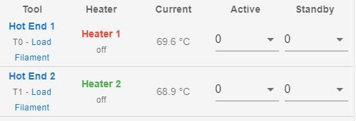
Thank your for the help getting this sorted. -
@thunderrunna said in Error:Invalid Remote Handle:
Paneldue 7i there is an error of "Warning: failed to parse response k{ in state 12
please can you open another question about this in the PanelDue Category. @mfs12 will need to advise.
@thunderrunna said in Error:Invalid Remote Handle:
When homing z (bl touch) there is an error of "failed to enable endstops". Is there something to be changed in the homing files to suit the 1xd boards/bltouch also the 1xd boards in general?
I assume you home X and Y before Z? do you get this error when homing X or Y?
@thunderrunna said in Error:Invalid Remote Handle:
Have tried the thermistors on "temp out 1" for both boards and both still read in the 69 - 70 degree range. have triple checked the values again the configurator and slice engineering website.
Looking at slice engineering's website the 300C thermistor should be:
T100000 B4680 C6.455513e-8 -
@t3p3tony X axis moves and homes (double tap) as it should, y axis does not move (integrated stepper driver needs to be re configured/awaiting on cable however x axis moves as requested when connected to y axis driver and manually touch y end stop to trigger). Bltouch probe can be deployed and retracted via g code but when z home or home all are requested, the endstop error occurs. Have changed the thermistor values and they change 1 degree. Re run the thermistor calibration cycle and still no change.
-
 undefined Thunderrunna marked this topic as a question
-
@thunderrunna please post your homing files.
For the thermistor I am very surprised that changing the resistance from 500000 to 100000 only changed the room temperature measurement by 1C,
looking at the table posted by slice engineering:
https://docs.google.com/spreadsheets/d/1904x5JK-Sup-cX5DqHiiZWaFVTK6_PQBFxgi_6yXEJw/edit#gid=934228925and extrapolating, a 100K thermistor, configured as a 500K thermistor would read about 70C at room temperature.
Worth measuring the resistance of your thermistors at room temperature.
-
@t3p3tony thank you for the help thus far.
I will get the homing files tomorrow when back at the workshop.I will also check the thermistor resistance tomorrow.
Thank you
-
@t3p3tony Im back again, Apologies for the delay,had some other things pop up and this took a side step.
So back onto the setup of all this today and have a few new issues. X,Y, Z axis all move and home, happy days. Extruders both work. However, the hotends overshoot =/- 10 degrees, fluctuate a few times and then sit 5 degrees above target temp. PID tune has been run three times and the problem persists. Not sure what to do here.
Until today, the heat bed and chamber heater (both 240v ac controlled via ssr) were not connected as this was the last step of the process. The heated bed was connected to "out 0" with power jumped from power in - out0 power in. The red led next to the out 0 connectors was illuminated as soon as the power was switched on and subsequently the ssr was then activated. Power down, disconnect the ssr. Power up, multimeter shows 23.9 volts coming from out 0. Commented out the bed heater in config.g to disable it and check if it was maybe a typo causing this. Nope. Removed the sd card, unplugged everything from the board, power up and still have the red illuminated. Checked with multimeter and there was 23.9v coming from the terminal. Bad mosfet?
Have a second board that is still in the box, pulled this out and bench tested it (no sd card, no connections other than 24v in with wire across from power in to out 0 power in), dont really know what the caper is, red led illuminated thus second bad mosfet on a brand new board. Back to config.g to switch the heated bed ssr output to out 7. re terminate wires and works as expected. Bit frustrated though with 2 boards having bad mosfets.onto my next query, 2 toolboard 1lc running bondtech lgx extuder with slice engineering hotends, 50w heater and 300 degree thermistors. As outlined above, hotends are over shooting initially and staying above the target temp. The hotend cooling fans are setup to be thermo controlled, however this isnt the case, they are either on from startup regardless or dont switch on at all. a virtual temperature sensor was also created for the mcu to control a fan in the elctronics area to keep the boards cool, set at 40, this fan stays permanently on. Again, maybe a type or misread in the config.g?
config.g attached below
; Configuration file for Duet 3 (firmware version 3.3) ; executed by the firmware on start-up ; ; generated by RepRapFirmware Configuration Tool v3.3.5 on Sat Nov 20 2021 09:35:37 GMT+0800 (Australian Western Standard Time) ; General preferences M575 P1 S1 B57600 ; enable support for PanelDue G90 ; send absolute coordinates... M83 ; ...but relative extruder moves M550 P"Duet 3" ; set printer name ; Drives G4 S2 ; Wait for expansion boards to start M569 P40.0 S0 R0 T2.5:2.5:5:0 ; physical drive X 40.0.0 goes forwards, requires an active high enable M569 P41.0 S1 R0 T2.5:2.5:5:0 ; physical drive Y 41.0 goes forwards, requires an active high enable M569 P42.0 S0 R1 T5.0:5.0:5:0 ; physical drive Z 42.0 goes forwards, requires an active low enable M569 P20.0 S0 ; physical drive extruder 1 20.0 goes forwards M569 P21.0 S0 ; physical drive extruder 2 21.0 goes forwards M584 X40.0 Y41.0 Z42.0 E20.0:21.0 ; set drive mapping M350 X16 Y16 Z1 E16:16 I0 ; configure microstepping without interpolation M92 X275.00 Y111.00 Z600.00 E400.00:400.00 ; set steps per mm ;M566 X900.00 Y600.00 Z60.00 M566 E120.00:120.00 ; set maximum instantaneous speed changes (mm/min) ;M203 X600.00 Y600.00 Z300.00 M203 E1200.00:1200.00 ; set maximum speeds (mm/min) ;M201 X500.00 Y500.00 Z20.00 M201 E250.00:250.00 ; set accelerations (mm/s^2) M906 E600:600 I30 ; set motor currents (mA) and motor idle factor in per cent M84 S30 ; Set idle timeout ; Axis Limits M208 X0 Y0 Z0 S1 ; set axis minima M208 X580 Y600 Z600 S0 ; set axis maxima ; Endstops M574 X1 S1 P"20.io2.in" ; configure switch-type (e.g. microswitch) endstop for low end on X via pin 121.io2.in M574 Y1 S1 P"io1.in" ; configure switch-type (e.g. microswitch) endstop for low end on Y via pin io1.in ; Z-Probe M950 S0 C"20.io0.out" ; create servo pin 0 for BLTouch M558 P9 C"20.io0.in" H5 F120 T6000 ; set Z probe type to bltouch and the dive height + speeds G31 P500 X0 Y0 Z2.5 ; set Z probe trigger value, offset and trigger height M557 X15:585 Y15:585 S50 ; define mesh grid ; Heaters M308 S0 P"temp0" Y"thermistor" T10000 B3988 ; configure sensor 0 as thermistor on pin temp0 M308 S0 T250000 B4138 R4700 ; Set thermistor + ADC parameters for heater 0 M950 H0 C"out7" T0 ; create bed heater output on !out7 and map it to sensor 0 M307 H0 B0 R0.551 C275.9 D9.13 S1.00 ; disable bang-bang mode for the bed heater and set PWM limit M140 H0 ; map heated bed to heater 0 M143 H0 S120 ; set temperature limit for heater 0 to 120C M308 S1 P"20.temp1" Y"thermistor" T100000 B4680 C6.455513e-8 ; configure sensor 1 as thermistor on pin 20.temp0 M950 H1 C"20.out0" T1 ; create nozzle heater output on 20.out0 and map it to sensor 1 M307 H1 B0 R2.941 C260.3:256.2 D7.68 S1.00 V23.2 ; disable bang-bang mode for heater and set PWM limit Tool 0 M143 H1 S310 ; set temperature limit for heater 1 to 310C M308 S2 P"21.temp0" Y"thermistor" T100000 B4680 C6.455513e-8 ; configure sensor 2 as thermistor on pin 21.temp0 M950 H2 C"21.out0" T2 ; create nozzle heater output on 21.out0 and map it to sensor 2 M307 H2 B0 R2.990 C272.3:266.9 D7.61 S1.00 V23.0 ; disable bang-bang mode for heater and set PWM limit Tool 1 M143 H2 S310 ; set temperature limit for heater 2 to 310C M308 S3 P"temp1" Y"thermistor" T100000 B4725 C7.06e-8 ; configure sensor 3 as thermistor on pin temp1 M950 H3 C"out1" T3 ; create chamber heater output on out1 and map it to sensor 3 M307 H3 B0 R1.852 C43.3 D1.97 S1.00 ; enable bang-bang mode for the chamber heater and set PWM limit M141 H3 ; map chamber to heater 3 M143 H3 S70 ; set temperature limit for heater 3 to 70C M308 S4 Y"mcutemp" A"mcutemp" ; virtual temperature sensor for Duet3 MB ; Fans M950 F0 C"20.out1" Q500 ; create fan 0 on pin 20.out1 and set its frequency M106 P0 S0 H0 T45 ; set fan 0 value. Thermostatic control is turned on M950 F1 C"21.out2" Q500 ; create fan 1 on pin 21.out2 and set its frequency M106 P1 S1 H0 T45 ; set fan 1 value. Thermostatic control is turned on M950 F2 C"21.out1" Q500 ; create fan 2 on pin 21.out1 and set its frequency M106 P2 S1 H1 T45 ; set fan 2 value. Thermostatic control is turned on M950 F3 C"out2" Q500 ; create fan 3 on pin out2 and set its frequency - Electronics Enclosure M106 P3 T40 H3 ; set fan 3 temperature. Thermostatic control is turned on ; Tools M563 P0 S"Hot End 1" D0 H1 F0 ; define tool 0 G10 P0 X50 Y25 Z0 ; set tool 0 axis offsets G10 P0 R0 S0 ; set initial tool 0 active and standby temperatures to 0C M563 P1 S"Hot End 2" D1 H2 F0 ; define tool 1 G10 P1 X80 Y25 Z0 ; set tool 1 axis offsets G10 P1 R0 S0 ; set initial tool 1 active and standby temperatures to 0C ; Custom settings are not defined code_text -
undefined Shoki referenced this topic