• Tags
  • Documentation
  • Order
  • Register
  • Login
Duet3D Logo Duet3D
  • Tags
  • Documentation
  • Order
  • Register
  • Login

Strange layer offset on coreXY

Scheduled Pinned Locked Moved Solved
Firmware installation
10
38
1.9k
Loading More Posts
  • Oldest to Newest
  • Newest to Oldest
  • Most Votes
Reply
  • Reply as topic
Log in to reply
This topic has been deleted. Only users with topic management privileges can see it.
  • undefined
    whosrdaddy
    last edited by 28 Nov 2021, 15:42

    This is a mechanical problem, not an electronics problem.
    Can we see pictures of your belt setup. I guess one or more belts paths are not perpendicular to X or Y motion...

    undefined undefined 2 Replies Last reply 28 Nov 2021, 15:55 Reply Quote 0
    • undefined
      JoergS5 @whosrdaddy
      last edited by 28 Nov 2021, 15:55

      @whosrdaddy that's a good point, and the best description I know about it is in https://drmrehorst.blogspot.com/2018/08/corexy-mechanism-layout-and-belt.html

      1 Reply Last reply Reply Quote 0
      • undefined
        rjenkinsgb @whosrdaddy
        last edited by rjenkinsgb 28 Nov 2021, 15:57

        @whosrdaddy said in Strange layer offset on coreXY:

        This is a mechanical problem, not an electronics problem.

        The "cube" appears to be slanted, not just deformed scale-wise - or is it just the photo angle?

        Any mechanical setup or steps per mm error would give x-y distortion, but not drift, surely?
        A given X-Y point should always be the same, no matter how far off true position it is??

        If there is no slant or layer drift, and only shape distortion, then scaling and mechanics are the likely cause.

        Robert J.

        Printers: Overlord pro, Kossel XL+ with Duet 6HC and "Frankentron", TronXY X5SA Pro converted to E3D toolchange with Duet 6HC and 1LC toolboards.

        1 Reply Last reply Reply Quote 0
        • undefined
          mrehorstdmd
          last edited by mrehorstdmd 28 Nov 2021, 16:13

          I would try modifying the step/dir/en timing parameters in the M569 statements. You may be operating right at the limits of the external hardware. Try increasing the values until they are well above the minimum specs in the driver manual. In my sand table with servomotors I use

          M569 P5 S1 R0 T4.0:5.0:6.0:12.0 ; drive 5 reverse, lo enable, timing parameters for servomotors
          M569 P6 S1 R0 T4.0:5.0:6.0:12.0 ; drive 6 reverse, lo enable, timing parameters for servomotors

          These values allow the motors to hit their back-emf speed limit of 3k rpm.

          Some photos of the printer might be useful...

          https://drmrehorst.blogspot.com/

          undefined 1 Reply Last reply 29 Nov 2021, 16:02 Reply Quote 1
          • undefined
            DVD479
            last edited by 28 Nov 2021, 19:18

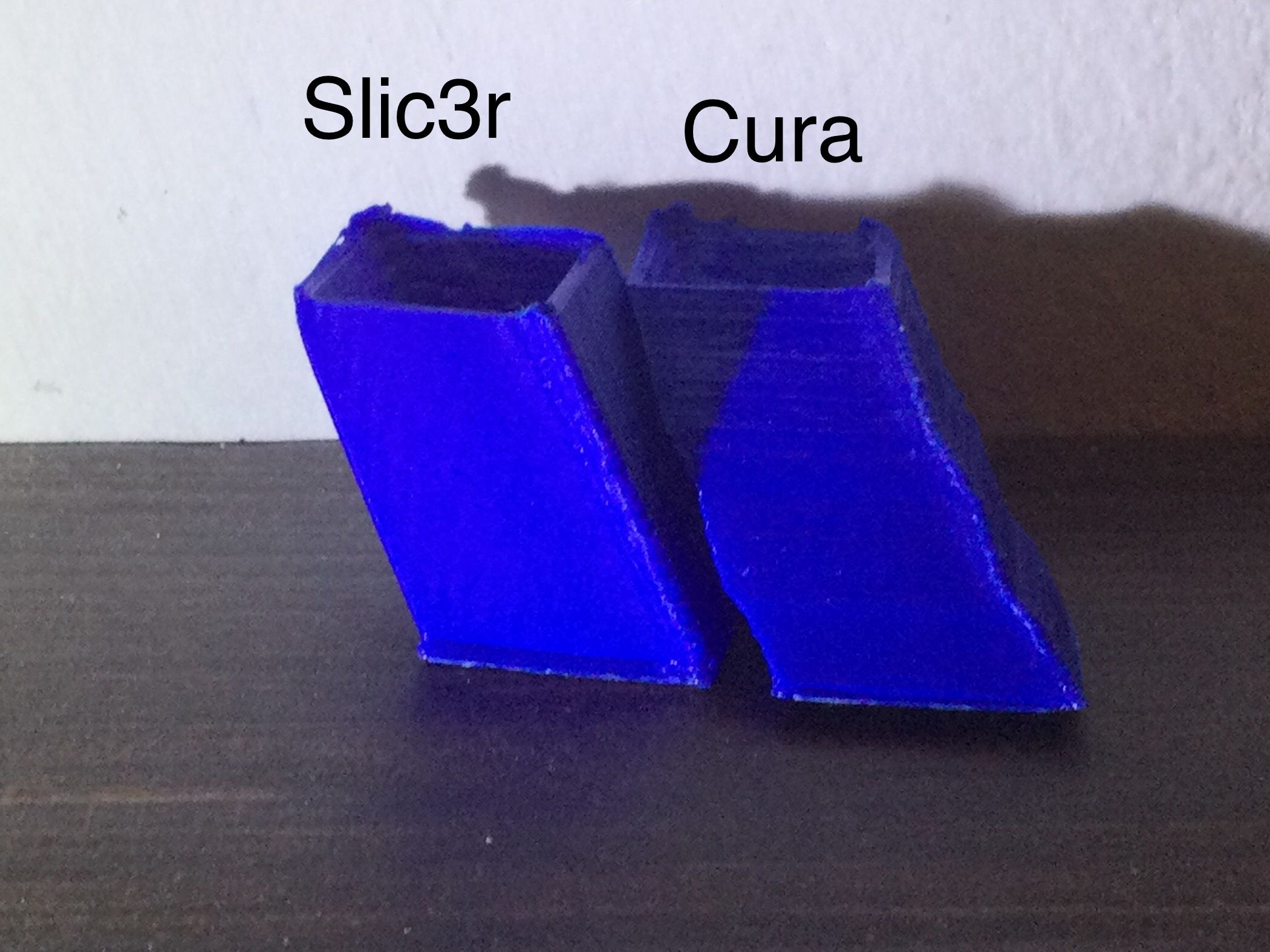
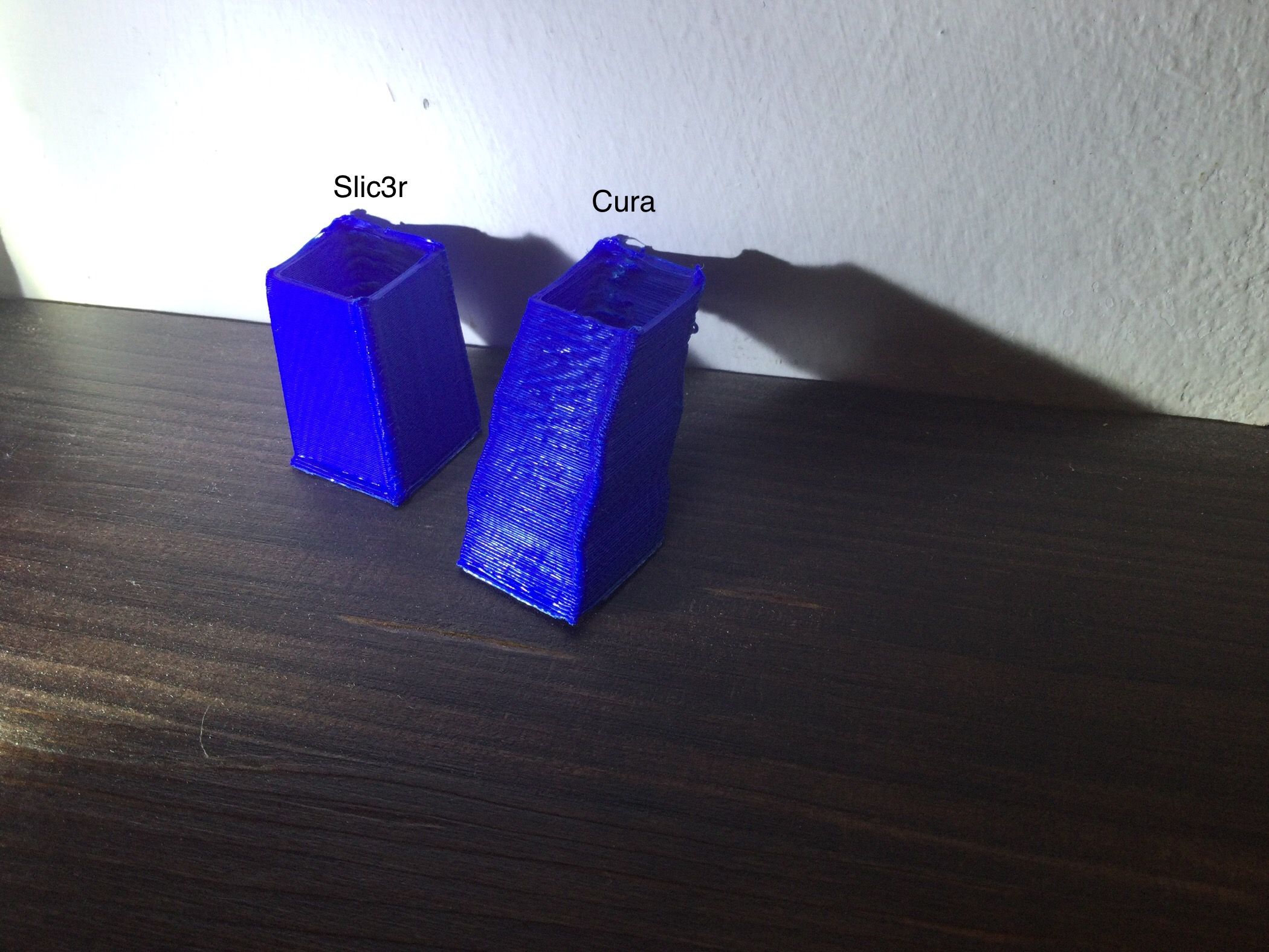
            thanks everyone for the advice. at the moment I can't send the photo of the corexy logic used but I think the problem is not due to the positioning of the belts since I used a scheme similar to the voron 2.4. I had also tried to increase the delay times of the motors and also reduced the microsteps to reduce the data flow. I am attaching some photos to show the problem that I have honestly never encountered. I fear it is a software problem and not a mechanical one because as you can see from the photos keeping the same mechanical configuration, generating the gcode with CURA and slic3r I got a different result. do you think it could be a problem of the slicer with the corexy logic?4D6FF8D5-87D8-4E26-99F6-A10359D55B9A.jpeg 834679A8-6AF6-425A-959E-F0E2AEA4B619.jpeg

            undefined 1 Reply Last reply 28 Nov 2021, 19:27 Reply Quote 0
            • undefined
              JoergS5 @DVD479
              last edited by 28 Nov 2021, 19:27

              @dvd479 said in Strange layer offset on coreXY:

              generating the gcode with CURA and slic3r I got a different result.

              you can analyze the two g-codes for differences, they are simple text files. Probably at the beginning is something different. To help you look into it, please publish it.

              The corexy logic cannot be the reason, because g-code files contain cartesian coordinates and the firmware translates it into the specific kinematics like corexy.

              1 Reply Last reply Reply Quote 0
              • undefined
                DVD479
                last edited by 28 Nov 2021, 19:49

                slic3rCube.gcode CuraCube.gcode

                1 Reply Last reply Reply Quote 0
                • undefined
                  DVD479
                  last edited by 28 Nov 2021, 19:58

                  these are the two files, however, I don't know if the engine of the two slicers behave in an equivalent way, giving similar Cartesian coordinates as values.

                  I wanted to hear your opinion regarding a doubt, in your opinion it is possible that in a Gcode file a certain coordinate with the information for XYE is repeated for each layer or it is not probable as a repetition

                  undefined 3 Replies Last reply 28 Nov 2021, 20:54 Reply Quote 0
                  • undefined
                    JoergS5 @DVD479
                    last edited by JoergS5 28 Nov 2021, 20:54

                    This post is deleted!
                    1 Reply Last reply Reply Quote 0
                    • undefined
                      JoergS5 @DVD479
                      last edited by 28 Nov 2021, 21:27

                      @dvd479 I am wondering why your printout is so height, when it should be a cube. Either XY print much shorter than calculated or your Z layer heights are heigher than 20 mm. Can you please tell me the dimensions of the printouts?

                      Do you have any gears at X, Y or Z steppers or Nema steppers with 400 instead of 200 steps?

                      1 Reply Last reply Reply Quote 0
                      • undefined
                        JoergS5 @DVD479
                        last edited by JoergS5 28 Nov 2021, 21:34

                        @dvd479 Something is wrong with your config.g:

                        M669 K1 ; switch to CoreXY mode
                        M569 P5 T2.5:2.5:5:5 S0 ; physical drive 0 goes backwards
                        M569 P6 T2.5:2.5:5:5 S1 ; physical drive 1 goes backwards
                        M569 P2 S0 ; physical drive 2 goes backwards
                        M569 P3 S1 ; physical drive 3 goes forwards
                        M584 X6 Y5 Z7 E8 ; set drive mapping

                        Z7 and E8 have no mapping to steppers, there are no M569 definitions.

                        M350 Z2 with M92 Z80 is also a strange combination, what do you use for Z?

                        1 Reply Last reply Reply Quote 0
                        • undefined
                          mrehorstdmd
                          last edited by 28 Nov 2021, 22:12

                          Photos of the printer...?

                          https://drmrehorst.blogspot.com/

                          1 Reply Last reply Reply Quote 0
                          • undefined
                            DVD479
                            last edited by 29 Nov 2021, 09:08

                            the stl file represents a cube with 20mm side, for the z I had used M350 Z2 combined with M92 Z80 as I set the driver at 400 microstep and having a screw with 5mm pitch doing the calculation should result 400/5 = 80 which it should be the microsteps needed by the Z to move 1mm,
                            the strange thing is that the cube is 20mm high and the sides are also 20mm the difference is in the printing angle which with slic3r is much lower while with CURA the deviation is greater

                            thanks for the tips

                            ? undefined 2 Replies Last reply 29 Nov 2021, 15:15 Reply Quote 0
                            • undefined
                              JoergS5
                              last edited by JoergS5 29 Nov 2021, 09:46

                              your print bed could also move,resulting in this shift. Or while printing the object is moved. Images would definitely help now to think about possible reasons.

                              About slic3r versus Cura, the g-code files have some different settings like bed temperature and filament temperature are different, this can be a reason. Thermal expansion of the bed e.g.

                              ? 1 Reply Last reply 29 Nov 2021, 12:47 Reply Quote 0
                              • ?
                                A Former User @JoergS5
                                last edited by 29 Nov 2021, 12:47

                                @joergs5

                                So I have also layer shifts BUT ONLY when I´m switching tools.
                                May we have a similar problem.....
                                I slice with cura.

                                Richard

                                undefined 1 Reply Last reply 29 Nov 2021, 14:35 Reply Quote 0
                                • undefined
                                  JoergS5 @A Former User
                                  last edited by 29 Nov 2021, 14:35

                                  @gruna-studio please talk with @DVD479 , he has the problem.

                                  1 Reply Last reply Reply Quote 0
                                  • ?
                                    A Former User @DVD479
                                    last edited by 29 Nov 2021, 15:15

                                    @dvd479 So I have also layer shifts BUT ONLY when I´m switching tools.
                                    May we have a similar problem.....
                                    I slice with cura.

                                    Richard

                                    Any news?
                                    I´m also frustrated about the offset.

                                    1 Reply Last reply Reply Quote 0
                                    • undefined
                                      deckingman @DVD479
                                      last edited by 29 Nov 2021, 15:38

                                      @dvd479 At what angle is the part sloping with respect to the build plate? By that I means, does it slope front to back, left to right, or at 45 degrees to X and Y? A picture of the machine with the completed part on the build plate would be a great help.

                                      Ian
                                      https://somei3deas.wordpress.com/
                                      https://www.youtube.com/@deckingman

                                      1 Reply Last reply Reply Quote 0
                                      • undefined
                                        Phaedrux Moderator @mrehorstdmd
                                        last edited by 29 Nov 2021, 16:02

                                        @mrehorstdmd said in Strange layer offset on coreXY:

                                        I would try modifying the step/dir/en timing parameters in the M569 statements. You may be operating right at the limits or the external hardware. Try increasing the values until they are well above the minimum specs in the driver manual. In my sand table with servomotors I use

                                        M569 P5 S1 R0 T4.0:5.0:6.0:12.0 ; drive 5 reverse, lo enable, timing parameters for servomotors
                                        M569 P6 S1 R0 T4.0:5.0:6.0:12.0 ; drive 6 reverse, lo enable, timing parameters for servomotors

                                        These values allow the motors to hit their back-emf speed limit of 3k rpm.

                                        Some photos of the printer might be useful...

                                        @DVD479 Have you taken a look at this yet?

                                        Z-Bot CoreXY Build | Thingiverse Profile

                                        1 Reply Last reply Reply Quote 0
                                        • undefined
                                          DVD479
                                          last edited by 29 Nov 2021, 16:16

                                          first of all I want to thank all those who have given me useful advice to solve my problem. in conclusion it seems that the problem is solved using Slic3r and going to set the value of XY SIZE COMPENSATION after several attempts and in this way I was able to solve the positioning error and the 20mm cube was printed correctly. I just have to test if this procedure works with other more complex files but I think it can work.Screenshot (18).png

                                          undefined 1 Reply Last reply 29 Nov 2021, 16:21 Reply Quote 0
                                          24 out of 38
                                          • First post
                                            24/38
                                            Last post
                                          Unless otherwise noted, all forum content is licensed under CC-BY-SA