Duet3D Logo Duet3D
    • Tags
    • Documentation
    • Order
    • Register
    • Login

    Extruder heater not showing up on DWC.

    Scheduled Pinned Locked Moved Solved
    Duet Web Control
    5
    16
    682
    Loading More Posts
    • Oldest to Newest
    • Newest to Oldest
    • Most Votes
    Reply
    • Reply as topic
    Log in to reply
    This topic has been deleted. Only users with topic management privileges can see it.
    • jay_s_ukundefined
      jay_s_uk @kcress
      last edited by

      @kcress ah, it's on the general settings tab.
      Your config looks correct in that it uses temp0 for the bed and temp1 for the hotend. So I would be looking at your wiring now.
      You're also probable not using B4138 thermistors so you need to update your config with the correct thermistor information.

      Owns various duet boards and is the main wiki maintainer for the Teamgloomy LPC/STM32 port of RRF. Assume I'm running whatever the latest beta/stable build is

      kcressundefined 1 Reply Last reply Reply Quote 0
      • kcressundefined
        kcress @jay_s_uk
        last edited by

        @jay_s_uk

        Thanks.
        The thermistors might be correct. Because I couldn't tell if they were the same or not I turned on the extruder heat, (50W), that got up to that fairly quickly while I was looking for the DWC version.

        Aw yes! I see it now. Thanks. Man-o-man, I looked for it everywhere - I thought.

        Duet Web Control 3.3.0

        kcressundefined 1 Reply Last reply Reply Quote 0
        • kcressundefined
          kcress @kcress
          last edited by

          Can't see a HW issue. I unplugged them from the original controller and moved them over to the 6HC.

          One sez "E Temp"
          the other "Bed Temp"

          ![alt text](Temps.jpg image url)

          jay_s_ukundefined 1 Reply Last reply Reply Quote 0
          • jay_s_ukundefined
            jay_s_uk @kcress
            last edited by

            @kcress can you take a picture from another angle? It's difficult to see where the wires go.
            Do you have the config from the other controller so you know what the right thermistors are?

            Owns various duet boards and is the main wiki maintainer for the Teamgloomy LPC/STM32 port of RRF. Assume I'm running whatever the latest beta/stable build is

            kcressundefined 1 Reply Last reply Reply Quote 0
            • kcressundefined
              kcress @jay_s_uk
              last edited by

              ![alt text](Temps2.jpg image url)

              I found the original config!!

              ; Configuration file for Duet WiFi (firmware version 1.20 or newer)
              ; executed by the firmware on start-up
              
              ; --- general preferences ---
              M111 S0                                            ; debugging off
              G21                                                ; work in millimetres
              G90                                                ; send absolute coordinates
              M83                                                ; relative extruder moves
              M555 P2                                            ; set firmware compatibility to look like Marlin
              
              M667 S1                                            ; select CoreXY mode
              M208 X0 Y0 Z-5 S1                                   ; set axis minima to end of safe travel.
              M208 X310 Y308 Z400 S0                             ; set axis maxima to match endstop location.
              
              ; ---filament sensing---
              M591 D0 P1 C"e0_stop" S1
              
              ; Automatic power saving
              M911 S21 R23 P"M913 X0 Y0 G91 M83 G1 Z0 E-3 F1000"   ; Set voltage thresholds and actions to run on power loss
              
              ; --- endstops ---
              M574 X2 S1 P"^xstop"
              M574 Y2 S1 P"^ystop"
              
              ; Z-Probe
              M574 Z0 P"nil" ; no Z endstop switch, free up Z endstop input
              M558 P9 C"^zprobe.in" H5 R1 F120 T6000 A5 S0.02  ;BLTouch connected to Z probe IN pin
              M950 S0 C"duex.pwm5"
              
              M574 Z1 S0                               ; Set endstops controlled by probe
              
              G31 P50 X0 Y21 Z3.0                      ; Set Z probe trigger value, offset and trigger height
              M557 X15:285 Y15:285 S50                 ; Define mesh grid
              
              ; --- drives ---
              M569 P0 S1	; X
              M569 P1 S1	; Y
              ;M569 P2 S0	; Z
              M569 P3 S1	; E0
              ;M569 P4 S1	; E1
              ; -- duex --
              M569 P5 S1  ; Z5
              M569 P6 S0	; Z6
              M569 P7 S1	; Z7
              M569 P8 S0	; Z8
              
              M569 P2 R-1
              M569 P4 R-1
              M569 P9 R-1
              
              
              ; --- z-axis stepper leveling configuration ---
              M584 X0 Y1 E3 Z6:5:8:7                             ; four motors, at 5, 6, 7, and 8
              ;M671 X370:370:-50:-50 Y330:-65:-65:330 S20          ; Z belts at 4 corners
              M671 X-50:-50:370:370 Y330:-65:-65:330 S20          ; Z belts at 4 corners
              
              ; --- drive map ---
              ;    _______
              ;   | 6 | 7 |
              ;   | ----- |
              ;   | 5 | 8 |
              ;    -------
              ;     front
              
              M350 X16 Y16 Z16 E16 I1			                          ; microstepping with interpolation (I1)
              M92  X80 Y80 Z400 E400		                    	  ; steps per mm - with bt
              M566 X2000 Y2000 Z602.65 E1000		                 	  ; maximum instantaneous speed changes (mm/min) (jerk)
              M203 X20000 Y20000 Z1500 E10000	                	  	  ; maximum speeds (mm/min)
              M201 X1500 Y1500 Z500 E10000		                    	  ; accelerations
              M906 X1200 Y1200 Z1200 E1250 I60		              	  ; motor currents (mA) and motor idle factor in per cent
              
              M84 S60 				                                    ; set idle timeout


              ; Network
              
              M550 P"VIVEDINO"                         ; Set machine name
              
              M552 S1                                  ; Enable network
              
              M587 S"FORMBOT" P"zxcv555578"            ; Configure access point. You can delete this line once connected
              
              M586 P0 S1                               ; Enable HTTP
              
              M586 P1 S0                               ; Disable FTP
              
              M586 P2 S0                               ; Disable Telnet


              ; --- firmware retraction ---
              ;M207 S2.5 R0 F6500 T4500 Z0	                  ; [ Snnn positive length to retract, in mm ]
              					                          ; [ Rnnn positive or negative additional length to un-retract, in mm ]
              					                          ; [ Fnnn retraction feedrate, in mm/min ]
              					                          ; [ Tnnn feedrate for un-retraction if different from retraction, mm/min ]
              					                          ; [ Znnn additional zlift/hop ]
              
              ; --- heaters ---
              M308 S0 P"bed_temp" Y"thermistor" T100000 B4138 C0 R4700   ; define bed temperature sensor
              M308 S1 P"e0_temp" Y"thermistor" T100000 B4138 C0 R4700   ; define E0 temperature sensor
              M950 H0 C"bed_heat" T0 ; heater 0 uses the bed_heat pin, sensor 0
              M950 H1 C"e0_heat" T1 ; heater 1 uses the e0_heat pin and sensor 1
              M140H0
              
              ;M305 P0 T100000 B4138 C0 R4700                      ; set thermistor + ADC parameters for heater 0
              M307 H3 A-1 C-1 D-1                     		    ; set PID tuned settings for heater 0
              M143 H0 S125                                        ; set temperature limit for heater 0 to 120C
              ;M305 P1 T100000 B4138 C0 R4700                      ; set thermistor + ADC parameters for heater 1
              M307 H1 A517.3 C213.3 D11.1 V24.3 B0		    ; set PID tuned settings for heater 1
              M143 H1 S280                                        ; set temperature limit for heater 1 to 280C


              ; --- tools ---
              M563 P0 D0 H1                                       ; define tool 0
              G10 P0 X0 Y0 Z0                                     ; set tool 0 axis offsets
              G10 P0 R0 S0                                        ; set initial tool 0 active and standby temperatures to 0C
              
              ; --- fans ---
              M950 F0 C"fan0" ; Fan 0 uses the Fan0 output
              M950 F1 C"fan1" ; Fan 1 uses the Fan1 output
              M950 F2 C"fan2" ; Fan 2 uses the Fan2 output
              M106 P0 S0 I0 F500 H-1                             ; Set fan 0 value, PWM signal inversion and frequency. Thermostatic control is turned off
              M106 P1 S0.9 I0 F500 H1 T50                          ; Set fan 1 value, PWM signal inversion and frequency. Thermostatic control is turned on
              M106 P2 S1 I0 F500 H1 T50                          ; Set fan 2 value, PWM signal inversion and frequency. Thermostatic control is turned on
              
              M572 D0 S.15
              ;M572 D0 S.4							; Linear Advance
              ;M592 D0 A0.01 B0.0005					;nonlinear extrusion
              
              ; --- Set or report heating process parameters---
              M106 P3 I-1
              M106 P4 I-1
              M106 P5 I-1
              M106 P6 I-1
              M106 P7 I-1
              M106 P8 I-1
              
              ; --- RGB leds - White ---
              
              
              M950 P1 C"duex.fan4"
              M950 P2 C"duex.fan5"
              M950 P3 C"duex.fan6"
              M42 P1 S1.0 ; R-
              M42 P2 S1.0 ; G-
              M42 P3 S1.0 ; B-
              
              ; --- Case Fan ---
              M950 P5 C"duex.fan7"
              M42 P5 S0.0 ;
              
              ; --- Controller Fan ---
              M950 P4 C"duex.fan8"
              M42 P4 S0.5 ;
              
              M501
              

              Sooooo

              ; --- heaters ---
              M308 S0 P"bed_temp" Y"thermistor" T100000 B4138 C0 R4700   ; define bed temperature sensor
              M308 S1 P"e0_temp" Y"thermistor" T100000 B4138 C0 R4700   ; define E0 temperature sensor
              M950 H0 C"bed_heat" T0 ; heater 0 uses the bed_heat pin, sensor 0
              M950 H1 C"e0_heat" T1 ; heater 1 uses the e0_heat pin and sensor 1
              M140H0
              
              kcressundefined 1 Reply Last reply Reply Quote 0
              • kcressundefined
                kcress @kcress
                last edited by

                Changed it to this:

                M308 S0 P"temp0" Y"thermistor" T100000 B4138 C0 R4700  ; define bed temperature sensor
                M308 S1 P"temp1" Y"thermistor" T100000 B4138 C0 R4700  ; define E0 temperature sensor
                M950 H0 C"out0" T0                                     ; heater 0 uses the bed_heat pin, sensor 0
                M950 H1 C"out1" T1                                     ; heater 1 uses the e0_heat pin and sensor 1
                M307 H0 B1 S1.00                             ; enable bang-bang mode for the bed heater and set PWM limit
                M307 H1 B0 S1.00                             ; disable bang-bang mode for heater  and set PWM limit
                M140 H0                                      ; map heated bed to heater 0
                M140 H1                                      ; map EXTRUDER HEATER to heater 1


                No improvement. Still both are called "Heater 1" and I think show the extruder temp.

                ![alt text](ice_screenshot_20211127-013448.png image url)

                1 Reply Last reply Reply Quote 0
                • rjenkinsgbundefined
                  rjenkinsgb
                  last edited by

                  Take out the second M140 that has H1

                  M140 is specifically for the bed heater, not extruders.

                  Robert J.

                  Printers: Overlord pro, Kossel XL+ with Duet 6HC and "Frankentron", TronXY X5SA Pro converted to E3D toolchange with Duet 6HC and 1LC toolboards.

                  kcressundefined 1 Reply Last reply Reply Quote 1
                  • kcressundefined
                    kcress @rjenkinsgb
                    last edited by

                    @rjenkinsgb
                    EXCELLENT!

                    That did it.

                    Count this solved.

                    ![alt text](ice_screenshot_20211127-022407.png image url)

                    kcressundefined 1 Reply Last reply Reply Quote 0
                    • Phaedruxundefined Phaedrux marked this topic as a question
                    • Phaedruxundefined Phaedrux has marked this topic as solved
                    • kcressundefined
                      kcress @kcress
                      last edited by

                      A come-back note:

                      Noting that the heaters were reading too low. With the original Vivendo Troodon M308:

                      M308 S0 P"temp0" Y"thermistor" T100000 B4138 C0 R4700 ; define bed temperature sensor

                      The temperatures were corrected by removal of "R4700"
                      which is a compensation for what divider resistor is used on the Duet board or clone. Removing the R4700 and leaving it the default (whatever it is on the Duet 6HC) corrected the temp readings.

                      T3P3Tonyundefined 1 Reply Last reply Reply Quote 1
                      • T3P3Tonyundefined
                        T3P3Tony administrators @kcress
                        last edited by

                        @kcress thanks, yes they are 2k2 resistors on the 6HC which is why the documentation recommends not putting the R value in in recent firmware as the defaults should be correct.
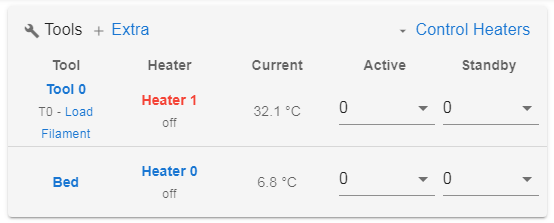
                        www.duet3d.com

                        1 Reply Last reply Reply Quote 0
                        • First post
                          Last post
                        Unless otherwise noted, all forum content is licensed under CC-BY-SA