An "hardware" advice for linear rails
-
@fcwilt said in An "hardware" advice for linear rails:
@thedragonlord
Hi,
Could you send me a STEP file of the gray parts holding the pulleys?
There is a arrangement I want to try out and post here for you to look at.
Frederick
I'm curios, what sort of arrangement were you thinking?
-
@achrn
Would you say, it'll be benefitical for existing printers made from 2020 extrusion to cover the unused T-slots with flat aluminum strips? Superglue works well on aluminum. -
@thedragonlord said in An "hardware" advice for linear rails:
@fcwilt said in An "hardware" advice for linear rails:
@thedragonlord
Hi,
Could you send me a STEP file of the gray parts holding the pulleys?
There is a arrangement I want to try out and post here for you to look at.
Frederick
I'm curios, what sort of arrangement were you thinking?
I will post a picture.
Frederick
-
@o_lampe said in An "hardware" advice for linear rails:
@achrn
Would you say, it'll be benefitical for existing printers made from 2020 extrusion to cover the unused T-slots with flat aluminum strips? Superglue works well on aluminum.That's an intersting idea I haven't considered before.
I wouldn't do it, because if the stiffness needed increasing I'd put in a bigger section. If you want to enhance stiffenss, increasing the overall dimension of the member beats everything (in general).
I agree cyanoacrylate adhesives work well on aluminium (both the actual aluminium and the oxide most of it is covered with). I note the bond of the oxide to underlying material is not great, so doing bonded aluminium joints properly is not straightforward - you'd want to degrease then gritblast then bond immediately. That's not a hobbyist-printer sort of process. If you omit the gritblast your bond strength will be limited to what peels the oxide off, and I don't know (offhand) what that value is.
Even if you can get enough bond strength, I think it would only be worthwhile if you were desperate for a small increase in stiffness for some reason (avoiding a particular resonant frequency, maybe) and trying to retrofit a solution to get maybe 30% more stiffness without changing the dimensions of the member much (e.g. if substituting a bigger member means you need to redesign a high proportion of something already built). It probably does more for torsion stiffness than flexural, but even then I think the same applies.
I will caveat my remarks by saying I'm principally civil / structural engineer, and most of my industry is very sceptical of bonded joints (though they all still drive to meetings in cars with bonded critical components, and fly on holiday in planes with bonded joints in the wings). I'm probably inherently averse to it - I know enough to be aware of lots of potential pitfalls.
-
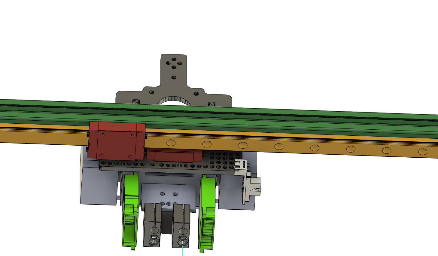
@thedragonlord said in An "hardware" advice for linear rails:
I'm curios, what sort of arrangement were you thinking?
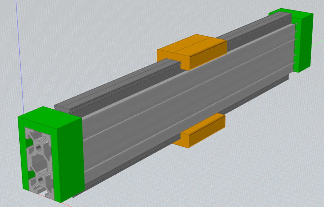
Here is a rough idea.
A 20x40 extrusion supports the 2 pieces of linear rail guide.
The green pieces are simply place holders for the actual pieces designed to mount the idlers.
-
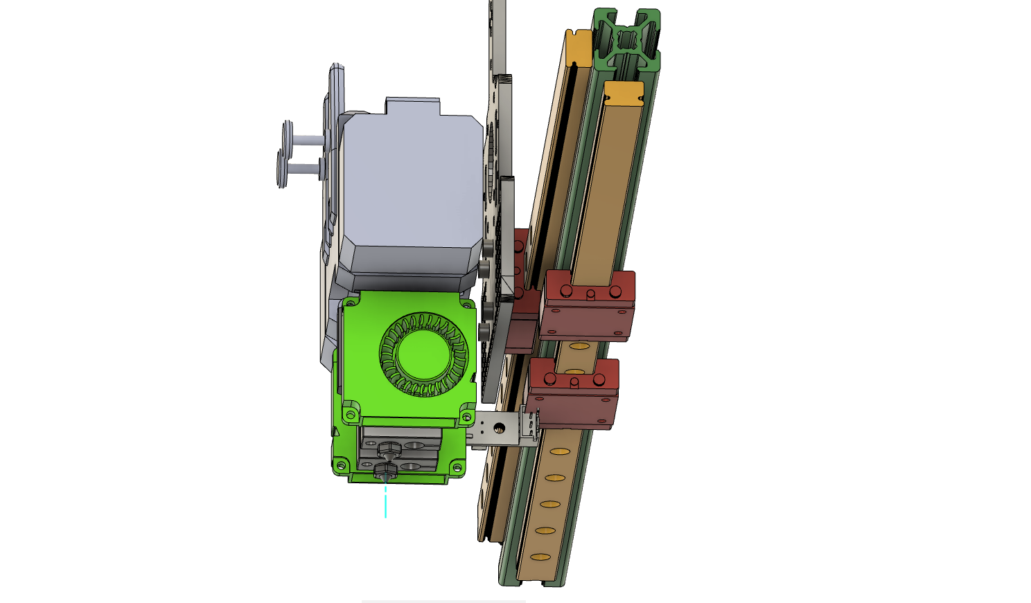
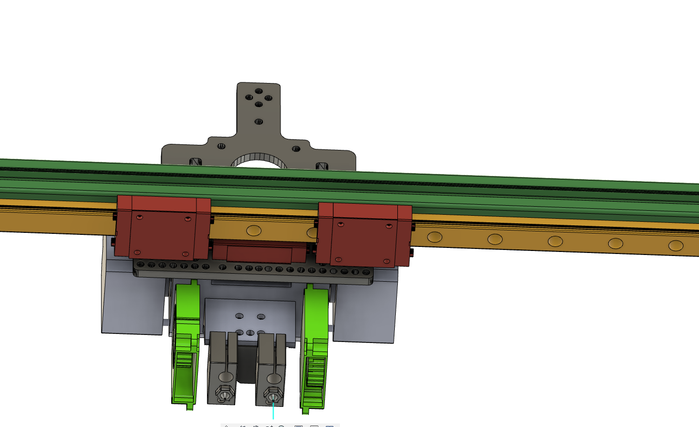
Good morning, waiting for the belt and the pulleys to arrive from Aliexpress I'm still experimenting a new solution to use two linear rails....I'm focusing on adding the second rail in the bottom side of the 2020 extrusion, the issue is that the two MGN12H cursor can be "overlapped" so I thought about theese two solutions: The first solution uses a single cursor in the front rail and two in the low rail; the second solution uses a single cursor even in the low rail. In your opinion what would be the best? I think that three cursors are maybe the best solution, but it could be maybe a "little" overkilled...on the other side maybe just a single cursor placed on the left (or the right) could maybe create a kind of problem? As you can see I've just thought about the rail and cursor(s) postitioning so I haven't designed the plate yet.....in your opinion what solution is better? As I said my actual rails are cheaper chinese peaces so I don't think that a single rail will be enough for the total weight...(i would like to print a little faster than 30 mm/s)
First solution:
Second solution:
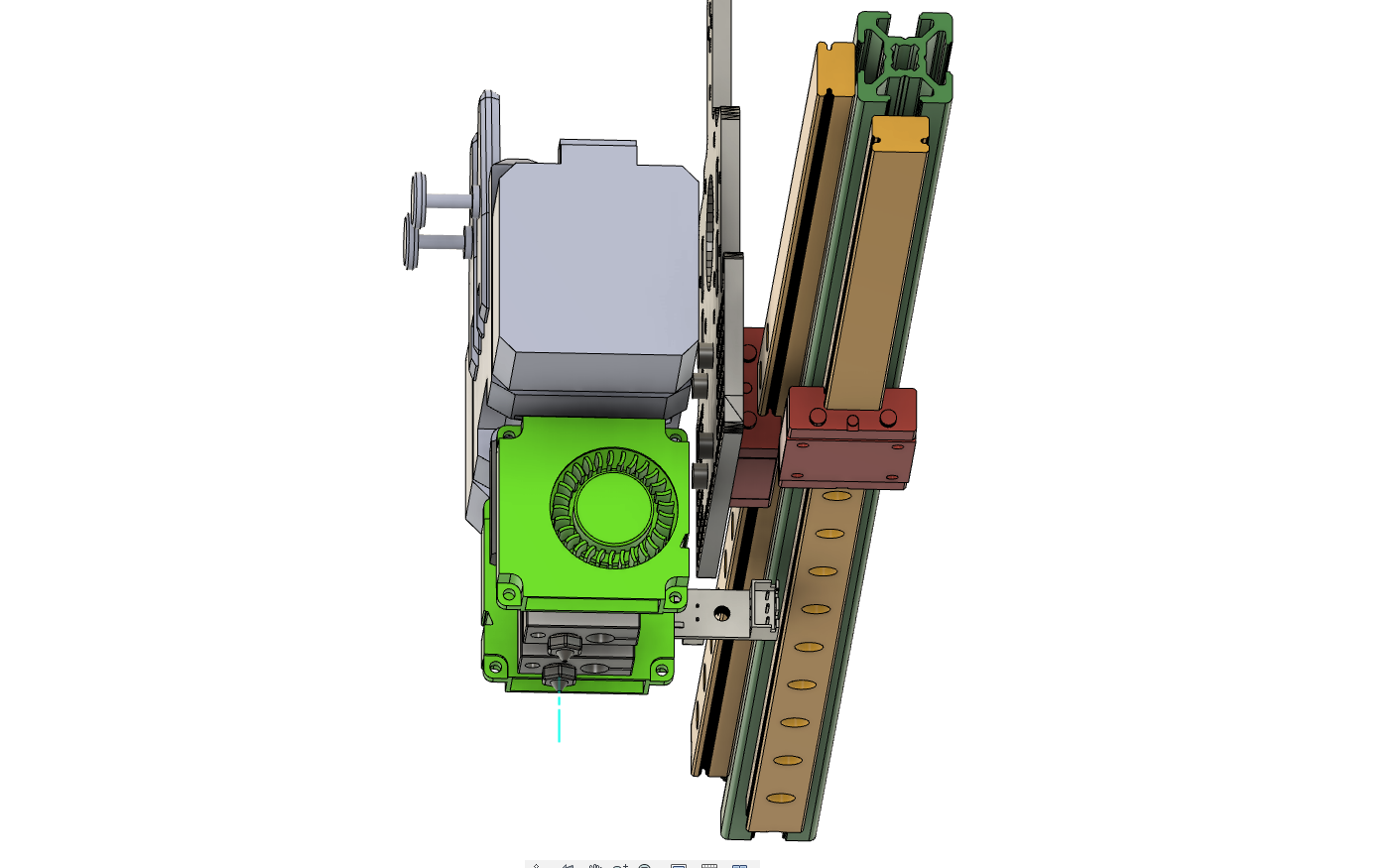
-
@thedragonlord
Don't see them as a single joint: each carrier has 4 screw holes
I've made the experience that two cheap carriers on one rail don't necessarily run smooth. I could only use the outer screw holes to fix the plate. But it still runs more stable, because of the wider stance. So I'd do it again the same way.You could also try one carrier per rail but put them as far apart as possible: one to the far left, the other to the far right.
-
@o_lampe said in An "hardware" advice for linear rails:
@thedragonlord
Don't see them as a single joint: each carrier has 4 screw holes
I've made the experience that two cheap carriers on one rail don't necessarily run smooth. I could only use the outer screw holes to fix the plate. But it still runs more stable, because of the wider stance. So I'd do it again the same way.You could also try one carrier per rail but put them as far apart as possible: one to the far left, the other to the far right.
You are absolutely right, I forgot to mention that I can't shift the front carrier left or right beacuse tha gray plate is made of alluminum and the existing holes doesn't fit the carrier if I shift it...I'd have to drill new holes in the middle of the existing ones and I don't have the right tools to do it precisely....
-
@thedragonlord
...then I'd go for three carriers and hope the best
-
@thedragonlord If you're willing to throw so much moving mass around, why not just use a single, larger linear guide? Everything would be easier and there would be no concerns about aligning multiple guide rails.
-
@mrehorstdmd said in An "hardware" advice for linear rails:
@thedragonlord If you're willing to throw so much moving mass around, why not just use a single, larger linear guide? Everything would be easier and there would be no concerns about aligning multiple guide rails.
I have to use what I already own, I have no extra money to spend right now