Duet 3 Mini 5+ for Single Arm Scara type printer
-
Hello everyone! I recently just finished building the hardware for a Scara type, but different from the two bar/parallel bar scara and the MP scara (I believe MP scara is different than X-Scara in terms of the how the motors arms are mounted). This 3d printer is called X-scara, link to it here (if that's okay I hope): https://www.thingiverse.com/thing:4500425/comments
I'm using Marlin, but it's having issues as usual. So of course, being the owners of four duet boards (two Duet Wifis, Duet Ethernet, and a Duet Maestro), I ordered a Duet 3 Mini 5+ from Spool3D, and should be here soon.
Okay background is done. My question is this. the Creator is nice enough to create a CAD in fusion with detailed instructions on his github, but I think there's something wrong with one of the endstop locations. I'm asking here because the creator can take quite awhile to respond, and while it's not his fault or anything, I'm trying to get this finished in two weeks. Looking at the CAD of the whole arm assembly, https://myhub.autodesk360.com/ue2a87a43/g/shares/SH919a0QTf3c32634dcf530f7dd13178bc27
You can see the endstop that uses hall effect (looks like two circluar with an arrow in each at the top of each arm part). They are both connected to same "rods" the one that moves the hotend. Is that correct? Should the top one be at the bottom instead? (You can see the 8mm steel rods, I've attached pictures to make it clearer as I suck at explaining things)
https://www.dropbox.com/s/c88cly4qcrnnkyl/2021-12-07 16.10.55.jpg?dl=0
https://www.dropbox.com/s/0eipmqwkznc4g37/2021-12-07 16.11.00.jpg?dl=0
https://www.dropbox.com/s/yo8shwanv4avas6/2021-12-07 16.11.10.jpg?dl=0
https://www.dropbox.com/s/7gzxbvur95vhifk/2021-12-07 16.11.25.jpg?dl=0
https://www.dropbox.com/s/k9c9zb6bw78sz6t/2021-12-07 16.11.25_LI.jpg?dl=0 (This one shows if the endstop should be moved to the one rod below).
Looking forward to make this work, excited to build a scara type printer (despite the complicated things that's making my brain really work)Thanks!
-
Yes, it does look confused to me; but without seeing the exact internal bearing arrangement and how the rigid gear at the first joint is attached and what supports the transfer shaft at that end, it's difficult to be sure exactly what is happening.
The 3D model makes it look as if the lower gear is mounted in the lower plate by its hub or boss, and the shaft is one piece, all the way through?
If it is, the limit would have to be on the arms rather than the shaft.
A cross section of that joint/shaft assembly would help.
As it has restricted motion in each axis as no slip, I'd consider having hall or optical home switches on the motor shafts, plus "home enable" switches on the main joints, for higher accuracy.
I can't see any simple switch giving repeatable high accuracy positioning on the large joints; a motor switch plus a joint switch so that is only enabled within the correct turn of the motor should give much better results.
-
I think it's okay for the sensor to be on the top because there is crosstalk between the two arms. You may need to follow a specific order of homing first the proximal and then the distal arm to make this work though.
-
Sorry for the delay, busy time of the year (report cards time etc).
I've take pictures of the thing to hopefully show the cross section of the belt paths better.
1st pic: https://www.dropbox.com/s/vyctnvsfld9p10a/2021-12-08 07.23.12.jpg?dl=0 the top belt is connected to the one that controls the hotend arm, the bottom belt is for the elbow arm.2nd pic: https://www.dropbox.com/s/qs5b5bkzlqf7y7y/2021-12-08 07.23.33.jpg?dl=0 same thing but I put a knife (I did this in a hurry as I'm at work right now) to show that the 8mm steel rod there is not connected, to the hotend arm, so when the elbow arm moves. it does move the hotend arm, but doesn't actually turn the hotend arm (I'm still trying to remember which is distal and proximal). So there is crosstalk.
Oh okay so yeah then the endstop is fine maybe?Here is the github for all the information, he also has excellent info which will help with the config settings (cause I am trying to port it to RRF, but have absolutely no idea for some things when I look at the scara wiki on duet wiki).
github: https://github.com/madl3x/x-scara
how to align (the degrees are hard to see, but one says -105 degrees for the center positionhttps://github.com/madl3x/x-scara/tree/master/images
https://github.com/madl3x/x-scara/blob/master/images/center_position.pngthe move in position picture is hard to see the number, but I think it says 50 degrees: https://github.com/madl3x/x-scara/blob/master/images/move_in_position.png
and his marlin firmware (based off the old 2.0.5 I believe, he is working on merging it to the newest 2.0.9.2) that I am using to port it over to RRF that I will need some help with. I know the length of the arms is 98mm for example, but other things like crosstalk etc I need help with.
https://github.com/madl3x/x-scara/blob/master/firmware/CONFIGURE.md
My mini 5+ should be here on Friday (wifi version). and I'll definitely require all your help on this for the endstop (I am using hall effect endstops as recommended by the creator himself).
So it looks like the sensor is fine at the top then?
-
This is from the github assembly drawings; it's inverted compared to the CAD views:
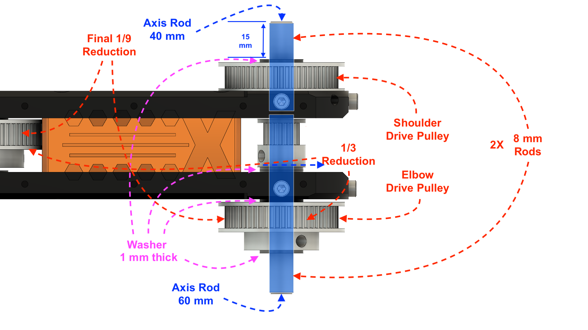
Allowing for (after) the inversion, the top shaft is the reduction drive to the hotend arm and the bottom shaft the first joint position.
It does appear that both switch actuators are working from the second joint, neither on the first.
I wonder if that first arm section was originally going to be the other way up?
As it is shown in this drawing, the top position would have been correct.
-
Yeah I knew I forgot something, this part in his drawing here that you've posted, either he made an error here, as you can see later on in the instructions here, it gets flipped the other way around. Hence why I am confused with the endstops, but his CAD drawing that I inked and as you said before also show the same thing, hence the confusion, and he hasn't responded in awhile, so I don't know.

https://github.com/madl3x/x-scara/blob/master/hardware/arm/images/assembly/Elbow_RodHub.pngAnyone familiar with SCARA can shed a light on this? It's not hard for me to flip the orientation, but yeah. Or is it as oliof said, it's okay because just need to follow a specific order of homing first the proximal then the distal arm? I couldn't find the setting in the marlin that he gave out here so I don't know either:
https://github.com/madl3x/x-scara/tree/master/firmware