Offset on height map
-
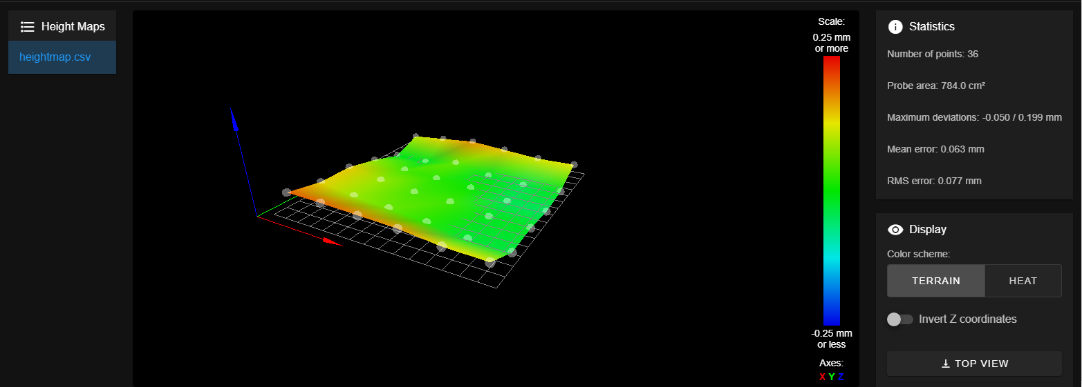
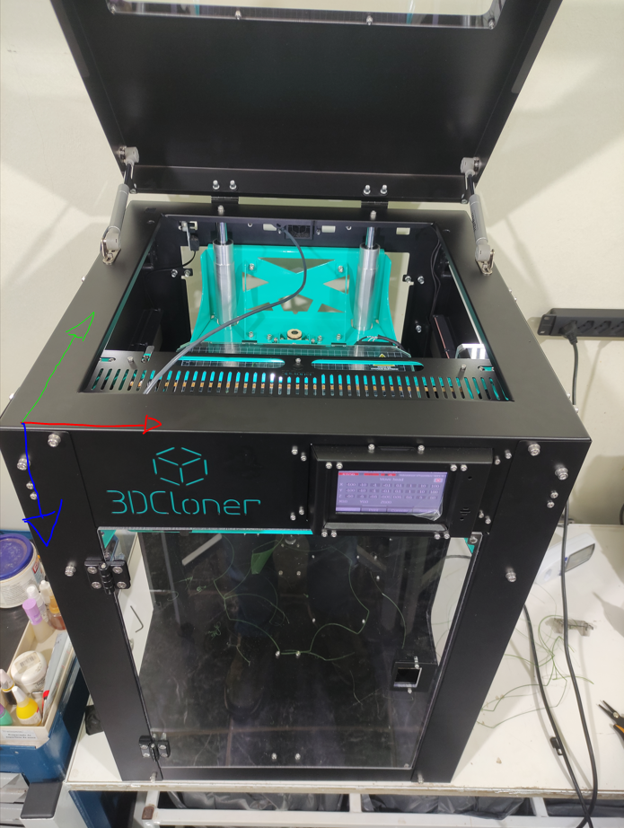
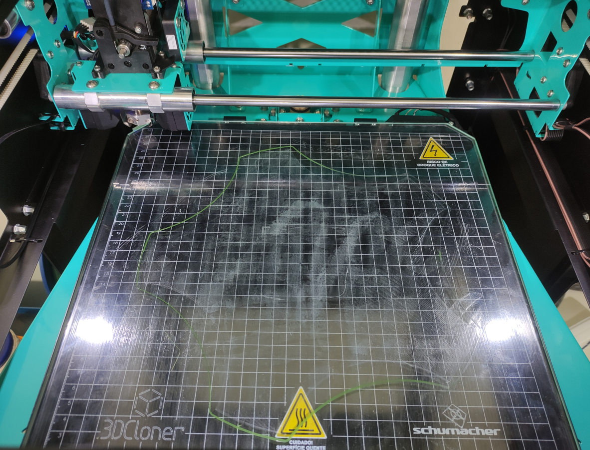
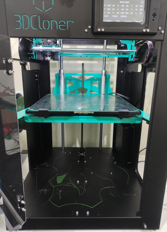
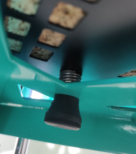
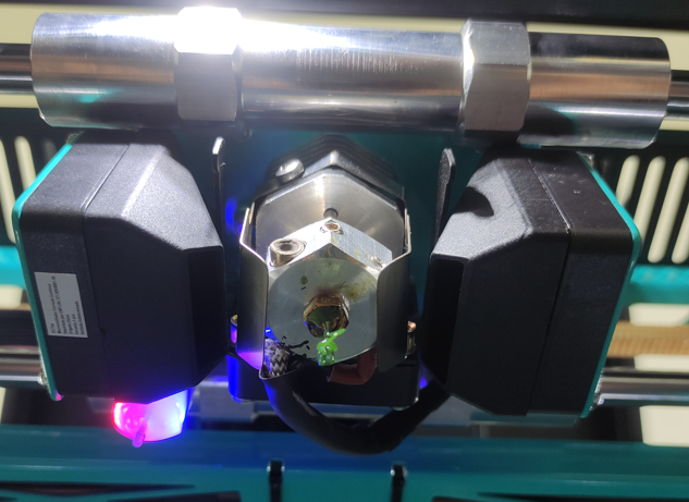
@fcwilt Hi, thanks for the reply. Our machine is this one, just a spindle shaft, with 4 points for manual leveling, and then automatic calibration. I'm sending photos of the table map, the z movement system, what the print looks like with this table map and what the head position is when all axes are at (0,0,0).
-
@diy-o-sphere I only use one spindle shaft, I don't know how it would be applicable. On the changed axes, I did the test of leaving it well uneven to make sure the sides are right, and they are, but the right side is always tighter than the left... as you can see in the photos in the other answer...
-
Thanks for the image of the height map.
Please post the actual heightmap.csv file so I can load into my viewer and look at it from all angles.
Also are the manual bed leveling adjustments - screws you can turn to level the bed?
Frederick
-
@fcwilt I'm going to post one more map because I'm doing some tests and I've already changed the map a little bit, but I didn't touch manual leveling.
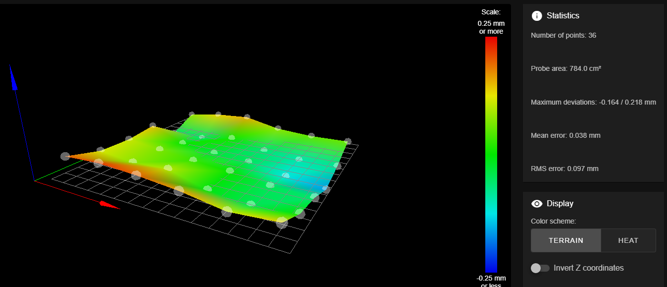
Here is the haight map
heightmap.csvAbout the manual leveling screws, there are 4 M5 knobs, they are items that we use in other products in our factory and not standard in the 3D printing market, but they work in the same way.
; General preferences G90 ; send absolute coordinates... M83 ; ...but relative extruder moves M550 P"3DCloner PLUS G4 V1.0" ; set printer name ; Network M552 S1 ; enable network M586 P0 S1 ; enable HTTP M586 P1 S0 ; disable FTP M586 P2 S0 ; disable Telnet ; Drives M569 P0 S0 ; physical drive 0 goes backrwards [*] M569 P1 S0 ; physical drive 1 goes backrwards [*] M569 P2 S0 ; physical drive 2 goes backrwards [*] M569 P3 S0 ; physical drive 3 goes backrwards [*] M584 X0 Y1 Z2 E3 ; set drive mapping M350 X16 Y16 Z16 E16 I1 ; configure microstepping with interpolation M92 X106.67 Y106.67 Z1600.00 E94.4 ; set steps per mm M566 X1200.00 Y1200.00 Z180.00 E180.00 ; set maximum instantaneous speed changes (mm/min) M203 X48000.00 Y48000.00 Z900.00 E4200.00 ; set maximum speeds (mm/min) M201 X2000.00 Y2000.00 Z50.00 E960.00 ; set accelerations (mm/s^2) M906 X1000 Y1500 Z1200 E1200 I40 ; set motor currents (mA) and motor idle factor in per cent M84 S60 ; Set idle timeout ; Axis Limits M208 X-2.5 Y0 Z0 S1 ; set axis minima M208 X320 Y325 Z423 S0 ; set axis maxima ; Endstops M574 X1 S1 P"!xstop" ; configure active-high endstop for low end on X via pin xstop [*] M574 Y2 S1 P"!ystop" ; configure active-high endstop for high end on Y via pin ystop [*] M574 Z1 S2 ; configure Z-probe endstop for low end on Z ; Z-Probe M950 S0 C"exp.heater3" ; create servo pin 0 for BLTouch M558 P9 C"^zprobe.in" H4 F240 T19800 ; set Z probe type to bltouch and the dive height + speeds ;M558 P9 C"^zprobe.in" H4 F240 T19800 I1 ; set Z probe type to bltouch and the dive height + speeds G31 P500 X-34.3 Y31 Z2.195 ; set Z probe trigger value, offset and trigger height M557 X0:280 Y35:315 S56 ; define mesh grid ;M557 X35:315 Y0:280 S56 ; define mesh grid ; Bed M308 S0 A"Bed" P"bedtemp" Y"thermistor" T100000 B4138 R4700 ; set thermistor 0 [bed] M950 H0 C"bedheat" T0 ; heater 0 [bed] M140 H0 ; inicial temp M143 H0 S135 ; maximun heater temperature [bed] M307 H0 S0.2 B1 ; heater parameters ; Heaters M308 S1 A"E0" P"e0temp" Y"thermistor" T100000 B4138 R4700 ; set thermistor 1 [E0] M950 H1 C"e0heat" T1 ; heater 1 [E0] M307 H1 S1 B0 ; heater parameters M143 H1 S370 ; maximun heater temperature [E0] ; Fans M950 F0 C"fan0" Q500 ; fan 0 [printing cooling] M106 P0 S0 H-1 X127 ; set fan 0 value, PWM signal inversion and frequency. Thermostatic control is turned off M950 F1 C"fan1" Q500 ; fan 1 [other fans] M106 P1 S1 H1:1 T40 ; set fan 1 value, PWM signal inversion and frequency. Thermostatic control is turned on ; Tools M563 P0 D0 H1 F0 ; define tool 0 G10 P0 X0 Y0 Z0 ; set tool 0 axis offsets G10 P0 R0 S0 ; set initial tool 0 active and standby temperatures to 0C T0 ; select tool 0 ; Miscellaneous M575 P1 S1 B57600 ; enable support for PanelDue M501 ; load saved parameters from non-volatile memory M911 S21.0 R23.0 P"M913 X0 Y0 G91 M83 G1 Z3 E-5 F1000" ; set voltage thresholds and actions to run on power loss M591 D0 P1 C"e0stop" S1 ; set filament endstop -
Thank you for the file.
Do you use the Duet Manual Bed Leveling Assistant to adjust those leveling screws?
Frederick
Printers: a small Utilmaker style, a small CoreXY and a E3D MS/TC setup. Various hotends. Using Duet 3 hardware running 3.4.6
-
@fcwilt I don't use the assistant, in fact I found out about it today doing the research... Do you think it can solve it?
-
@fcwilt I did a test with the table very uneven to make sure it has the right references and not inverted, and they are right, even the result was identical to what I already sent.
She knows the map and everything, but the right side is tight and the left side is loose, funny that the front and back are fine, it looks like the x is inverted,
but only on the height map, because the piece is coming out right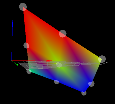
-
@3dcloner said in Offset on height map:
@fcwilt I don't use the assistant, in fact I found out about it today doing the research... Do you think it can solve it?
I use the bed leveling assistant to get the bed as level as possible.
Then I rely on the mesh bed compensation feature to deal with bed irregularities.
After using the bed leveling assistant you can create a 4 point height map just to verify that the bed is level to your satisfaction.
Then you can create the actual height map using a suitable number of points.
Frederick
Printers: a small Utilmaker style, a small CoreXY and a E3D MS/TC setup. Various hotends. Using Duet 3 hardware running 3.4.6
-
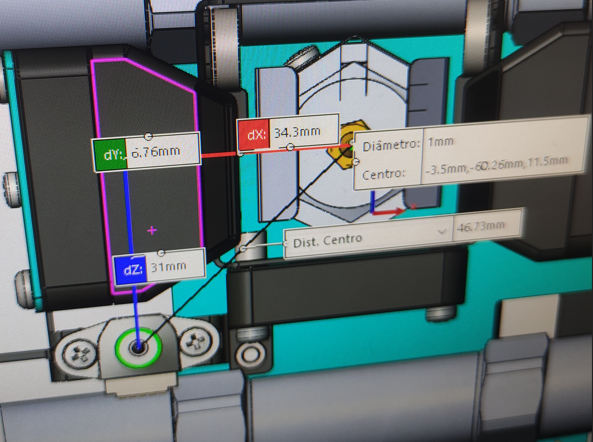
Can you share a photo of the print head showing the probe mounting position?
Are your probe XY offsets correct?
If you do a G30 S-1 test at multiple points on the bed do they stay consistent or do they change with XY position?
-
@fcwilt I used the assistant, but the problem persists, it seems that it has a tendency for the right side to be tight and the left side loose, both with the table level, with it not level, with the right side higher or the left higher, whatever, always the same result.
-
@fcwilt For sure!
In relation to the value it is correct, but it may be that I have inverted the meaning. But I've been trying a lot of things all day, and inverting the Z-Probe offsets was one of them.
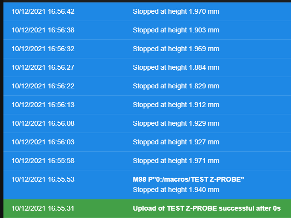
In relation to the G30 S-1. I made a macro with some dots, follow the code.
G28

G1 X35 Y100 Z15
G30 S-1
G1 X85 Y100 Z15
G30 S-1
G1 X170 Y100 Z15
G30 S-1
G1 X255 Y100 Z15
G30 S-1
G1 X320 Y100 Z15
G30 S-1

G1 X35 Y200 Z15
G30 S-1
G1 X85 Y200 Z15
G30 S-1
G1 X170 Y200 Z15
G30 S-1
G1 X255 Y200 Z15
G30 S-1
G1 X320 Y200 Z15
G30 S-1
this was the result (the height map was loaded)
-
@phaedrux When I see the symptoms, it seems that the spindle pitch is wrong when it comes to X compensation, because the Y axis is right and the Z steps per mm are right, I even saw it on the dial indicator. Besides the direction of rotation of the spindle is right, when it has to lower it it lowers, but not enough, the same thing when it needs to lower (on the X axis).
-
G31 P500 X-34.3 Y31 Z2.195
Based on your photo your G31 looks more or less correct.
Do you happen to have a M376 command anywhere in your startup gcode or elsewhere to configure some compensation taper?
-
@phaedrux Good morning, getting back to work! Good week to you!
About the G31 I even tried another configuration, as can be seen in config.g, but nothing changed.
About the M376, I don't use it, why? -
@phaedrux I'm taking a look at the Gcode G30 and its H parameter, it could be a solution, but I don't quite understand how I use it, could you help me?
-
@3dcloner said in Offset on height map:
M558 P9 C"^zprobe.in" H4 F240 T19800
I don't think G30 H is the solution. It seems as though your trigger heights are not consistent. I suggest modifying your M558 to try and improve it.
Try this line
M558 P9 C"^zprobe.in" H3 F60 T12000 A10 R0.2 S0.003 B0In your homeall you can speed up the homing process by using a faster speed for the first homing and then slow down for a repeat. like this
M558 F240 A1
G30
M558 F60 A10
G30 -
@phaedrux said in Offset on height map:
In your homeall you can speed up the homing process by using a faster speed for the first homing and then slow down for a repeat. like this
M558 F240 A1
G30
M558 F60 A10
G30Why that approach instead of Faaa:bbb?
Thanks.
Frederick
-
@fcwilt Habit.
-
@phaedrux @fcwilt Got it, I can adopt this homing with two speeds, it might be useful since the machine is quite big, etc.
But I have good news, our team has been working here since Friday trying to find the problem and we did it. The y-axis rods were slightly bent, which made the X-axis twist,
which consequently changed the distance between the nozzle and the Z-Probe along the X axis. Before, we had no problems with this slight misalignment because we didn't use a Z-Probe, and that's why it took us a while to check this alignment.Finally, thank you very much for your help and attention, I learned several new things in the process. Case closed.
-
 undefined Phaedrux marked this topic as a question
-
undefined Phaedrux has marked this topic as solved