Disabling Heater Fault
-
@sozkan What does the temperature graph look like during a print? Are there sudden excursions or gradual changes? Can you grab a screen shot and post it.
-
Also - following on from this thread, I wrote a little macro for heater tuning multiple zones. It's working well for me https://forum.duet3d.com/topic/26910/strategy-for-pid-tuning-multiple-heat-zones
-
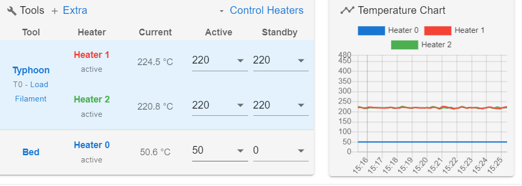
@deckingman The green curve represents the H2 is unstable during the print but after 2-3 hours of printing starts. I don't have a proper capture yet. While problematic during the printing, it is not in the active or standby with no printing. I doubted if the filament act like cooler while printing. I always find it time-based settings are not really perfect for such a situation.
It is the result of M307 Do you recommend me to reduce or increase some parameters?
M307 H2
Heater 2: heating rate 2.996, cooling rate 0.308, dead time 8.50, max PWM 0.40, mode PID, calibrated at 24.4V
Predicted max temperature rise 539°C
PID parameters: heating P7.0 I0.150 D41.7, steady P7.0 I0.308 D41.7
Excuse my ignorance but just asking: Since we have sensors, why it is crossing the limits and keep powering and fault detection can only find out? can it not be possible to get real-time thresholds to start energizing and stop between thresholds band? in this case, PID engine could only search for the thresholds gap?
-
@sozkan Please post your entire config.g and config-overide.g if you use it. Something looks wrong because the error messages relate to tool 0 not getting hot enough and a heater fault on heater 0 which exceeded it's allowable temperature. But heater 0 is normally the bed heater and wouldn't normally have an allowable temperature limit of 220 deg C, nor would it normally reach 245 deg C. So it looks like you might have something configured incorrectly.
-
config:
; Configuration file for Duet WiFi (firmware version 3)
; executed by the firmware on start-up
;
; generated by RepRapFirmware Configuration Tool v3.1.4 on Sun Sep 27 2020 20:52:39 GMT+0200 (Central European Summer Time)

; General preferences
G90                                                ; send absolute coordinates...
M83                                                ; ...but relative extruder moves
M550 P"Giant3D"                                    ; set printer name

M665 L1200.000:1200.000:1200.000 R603.000 H1298.25 B500.0 X0.000 Y0.000 Z0.000 ; Set delta radius, diagonal rod length, printable radius and homed height H1298.25 mm thermal expension.
M666 X0.000 Y0.000 Z0.000 A0.00 B0.00 ; put your endstop adjustments here, or let auto calibration find them


; Network
;M551 P""                                         ; set password
;M552 P0.0.0.0 S1                                 ; enable network, use DHCP
M552 S1                                            ; enable network
M586 P0 S1                                         ; enable HTTP
M586 P1 S0                                         ; disable FTP
M586 P2 S0                                         ; disable Telnet

M569 P9 S1 R1 T3:3:5:0      ; Extruder drive 0 goes Forward
;M569 P1 S1 R1 T3:3:5:0   ; Extruder drive 0 goes Forward
M569 P6 S1 R0 T10:10:10:10  ; X:A drive 1 goes Forward
M569 P7 S1 R0 T10:10:10:10  ; Y:B drive 2 goes Forward
M569 P8 S1 R0 T10:10:10:10  ; Z:C physical drive 3 goes Forward


M584 X6 Y7 Z8 E5                                   ; set drive mapping
M350 X1 Y1 Z1 E1 I1                                ; configure microstepping without interpolation

M92 X228.5714 Y228.5714 Z228.5714 E304.44        ; set steps per mm (3200/140) * 10 = 228.5714 ; 3200 step per rev ; 140 mm one rev pulley ;1:10 ratio gearbox
M566 X250.00 Y250.00 Z250.00 E250.00           ; set maximum instantaneous speed changes (mm/min)
M203 X2500.00 Y2500.00 Z2500.00 E2500.00           ; set maximum speeds (mm/min)
M201 X400.00 Y400.00 Z400.00 E1000.00           ; set accelerations (mm/s^2)
M906 X800 Y800 Z800 E800 I30                    ; set motor currents (mA) and motor idle factor in per cent
M84 S30                                            ; Set idle timeout

; Axis Limits
M208 Z0 S1                                         ; set minimum Z

; Endstops
M574 X2 S1 P"xstop"                                ; configure active-high endstop for high end on X via pin xstop
M574 Y2 S1 P"ystop"                                ; configure active-high endstop for high end on Y via pin ystop
M574 Z2 S1 P"zstop"                                ; configure active-high endstop for high end on Z via pin zstop

; Z-Probe
M558 P8 C"!zprobe.in" H50 F220 T1000   		   ; set Z probe type to unmodulated and the dive height + speeds
;M558 H30                                           ;*** Remove this line after delta calibration has been done and new delta parameters have been saved
G31 P500 X42.43 Y-42.43 Z1.71                       ; Circular 60 mm radious, 42.43 mm set Z probe trigger value, offset and trigger height
M557 R450 S200                                     ; define mesh grid

; Bed Heater
M308 S0 P"bedtemp" Y"thermistor" T100000 B3950    ; configure sensor 0 as thermistor on pin bedtemp
M950 H0 C"bedheat" T0                              ; create bed heater output on bedheat and map it to sensor 0
;M307 H0 B1 S1                                   ; enable bang-bang mode for the bed heater and set PWM limit
;M307 H0 A233.3 C508.3 D160 S1.00 V24.3 B1 ; older
M307 H0 B0 R0.059 C3538.6 D85.46 S1.00 V24.3

M140 H0                                            ; map heated bed to heater 0
M143 H0 S100                                       ; set temperature limit for heater 0 to 120C

; HotEnd
M308 S1 P"spi.cs1" Y"rtd-max31865"   		 	; configure sensor 1 as PT100 on pin e0temp
M308 S2 P"spi.cs2" Y"rtd-max31865"             ; configure sensor 2 as PT100 on pin e1temp
M950 H1 C"e0heat" T1                               ; create nozzle heater output on e0heat and map it to sensor 1
M950 H2 C"e1heat" T2                               ; create nozzle heater output on e1heat and map it to sensor 2
;M307 H1 B0 S0.50                                   ; disable bang-bang mode for heater  and set PWM limit
;M307 H2 B0 S0.50                                   ; disable bang-bang mode for heater  and set PWM limit

;M307 H1 A550 C180 D2.0 S0.35 V24.3 B0 ; older
;M307 H1 B0 R4.707 C287.9 D8.76 S0.35 V24.3 ; older 2
M307 H1 B0 R4.289 C188.3 D11.28 S0.35 V24.3
;M307 H2 A550 C239 D2.7 S0.5 V24.3 B0 ; older
;M307 H2 B0 R2.246 C352.7 D8.01 S0.50 V24.3 ; older 2
;M307 H2 B0 R2.804 C317.4 D8.25 S0.40 V24.2 ; older 3
 M307 H2 R2.996 K0.308:0.000 D8.50 E1.35 S0.40 B0 V24.4
;M301 H1 P5 I0.5 D1 ; Set PID values
;M301 H2 P5 I0.5 D1 ; Set PID values
M143 H1 S480 ;Set temperature max temp:
M143 H2 S480 ;Set temperature max temp:

; Fans
M950 F0 C"fan0" Q500                               ; create fan 0 on pin fan0 and set its frequency
M106 P0 S1 H2:1 T45                                ; set fan 0 value. Thermostatic control is turned on

M570 S240 ; wait 120 seconds for it to get close to the set temperature. If it takes longer than this, raise a heater fault.
;M570 H1 P4 T15 ; H heater, T tolerance degree, S second persist.
;M570 H1 P30 T30 S180 ; H heater, T tolerance degree, S second persist.
;M570 H2 P30 T30 S180 ; H heater, T tolerance degree, S second persist.


; Tools
M563 P0 D0 H1:2 F0 S"Typhoon"                      ; define tool 0
G10 P0 X0 Y0 Z0                                    ; set tool 0 axis offsets
G10 P0 R0 S0                                       ; set initial tool 0 active and standby temperatures to 0C


; Custom settings are not defined

; Miscellaneous
M575 P1 S1 B57600                                  ; enable support for PanelDue
;M500     ;  Save the parameters to non-volatile memory
M501                                               ; load saved parameters from non-volatile memory
M911 S10 R11 P"M913 X0 Y0 G91 M83 G1 Z3 E-5 F1000" ; set voltage thresholds and actions to run on power loss
T0                                                 ; select first tool
; Bunun maksadi sadece enable konumuna ulasmasi icin motorlari uyandirmak.
;G91                         ; relative positioning
;G1 H2 X-0.1 Y-0.1 Z-0.1 F1000      ; go down a few mm
config-override.g
; config-override.g file generated in response to M500
; This is a system-generated file - do not edit
; Delta parameters
M665 L1200.000:1200.000:1200.000 R603.000 H1298.250 B500.0 X0.000 Y0.000 Z0.000
M666 X0.000 Y0.000 Z0.000 A0.00 B0.00
; Heater model parameters
M307 H0 R0.059 K0.028:0.000 D85.46 E1.00 S1.00 B0
M307 H1 R4.289 K0.531:0.000 D11.28 E1.00 S0.35 B0 V24.3
M307 H2 R2.996 K0.308:0.000 D8.50 E1.35 S0.40 B0 V24.4
; Workplace coordinates
G10 L2 P1 X0.00 Y0.00 Z0.00
G10 L2 P2 X0.00 Y0.00 Z0.00
G10 L2 P3 X0.00 Y0.00 Z0.00
G10 L2 P4 X0.00 Y0.00 Z0.00
G10 L2 P5 X0.00 Y0.00 Z0.00
G10 L2 P6 X0.00 Y0.00 Z0.00
G10 L2 P7 X0.00 Y0.00 Z0.00
G10 L2 P8 X0.00 Y0.00 Z0.00
G10 L2 P9 X0.00 Y0.00 Z0.00
This the preview of 18 hours of non-print test. it is not failed yet. however, failure starts during the print.
-
@sozkan I don't see anything there which would explain the error message related to heater 0. Maybe the message itself is erroneous ??
That aside, I see that you are limiting the PWM value when you tune the heaters. Is there a reason for that? Have you tried tuning them with a PWM value of 1.0? If so, what happens?
I note also that you have commented out the fault detection lines for heaters 1 and 2. Given that you have two heater which interact with each other, you might want to re-instate those lines to give you that 30 degree allowable excursion.
Have you tried tuning the heaters using the macro I suggested?
-
@sozkan said in Disabling Heater Fault:
I have tested all versions of the firmware now I am at the latest one.
Can you test this beta version as well?
https://www.dropbox.com/sh/i5vox3xmkd55gaz/AAC19mI0WEC5GmEjLOBRbKs-a?dl=0
-
@deckingman said in Disabling Heater Fault:
@sozkan I don't see anything there which would explain the error message related to heater 0. Maybe the message itself is erroneous ??
That aside, I see that you are limiting the PWM value when you tune the heaters. Is there a reason for that? Have you tried tuning them with a PWM value of 1.0? If so, what happens?
I note also that you have commented out the fault detection lines for heaters 1 and 2. Given that you have two heater which interact with each other, you might want to re-instate those lines to give you that 30 degree allowable excursion.
Have you tried tuning the heaters using the macro I suggested?
As far as I remember PWM 1.0 is not suggested. However, I have tried today while testing your macros. I suddenly smell a smoke heavily cable burn type. But I have not seen any evidence of burn. It was a bit scary because all the bunch of cable together and it is high voltage!
Since there is not short yet, I am still trying to figure out what was burned. -
@phaedrux said in Disabling Heater Fault:
@sozkan said in Disabling Heater Fault:
I have tested all versions of the firmware now I am at the latest one.
Can you test this beta version as well?
https://www.dropbox.com/sh/i5vox3xmkd55gaz/AAC19mI0WEC5GmEjLOBRbKs-a?dl=0
Sure I have just updated. But now I gues the hothend H1 connector has burn! Because previously the smoke smell source has hotend PCB connector.
-
Do you see any visible damage? Best to disassemble completely and find the source if you haven't already. Waiting for a short may be waiting for destruction.
-
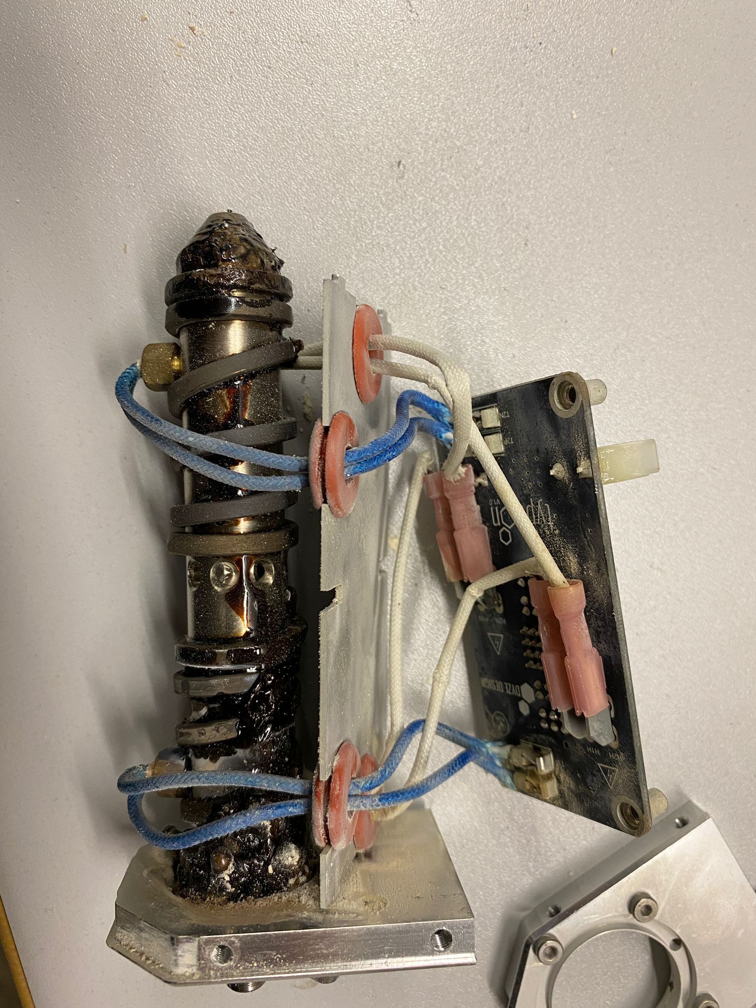
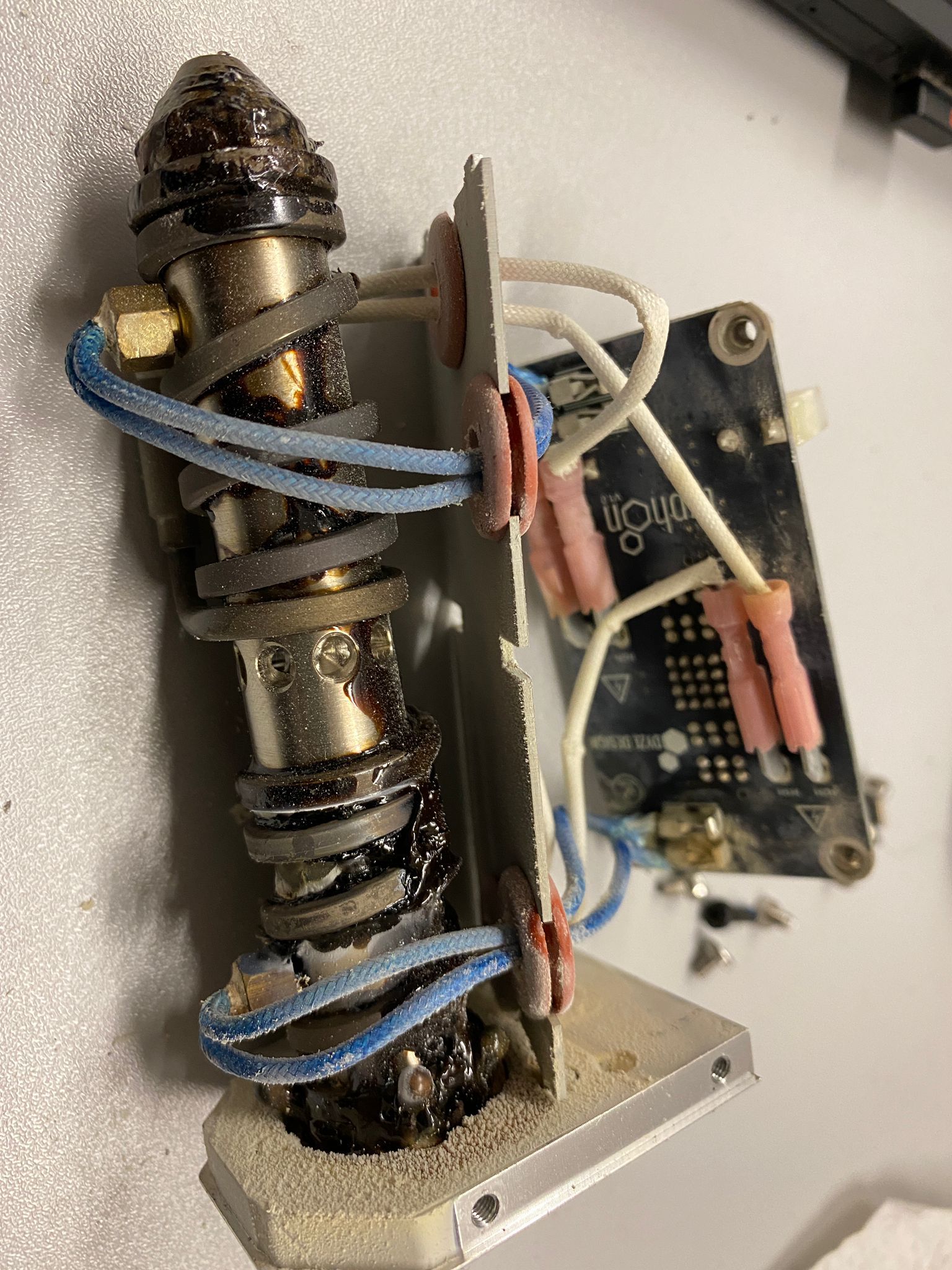
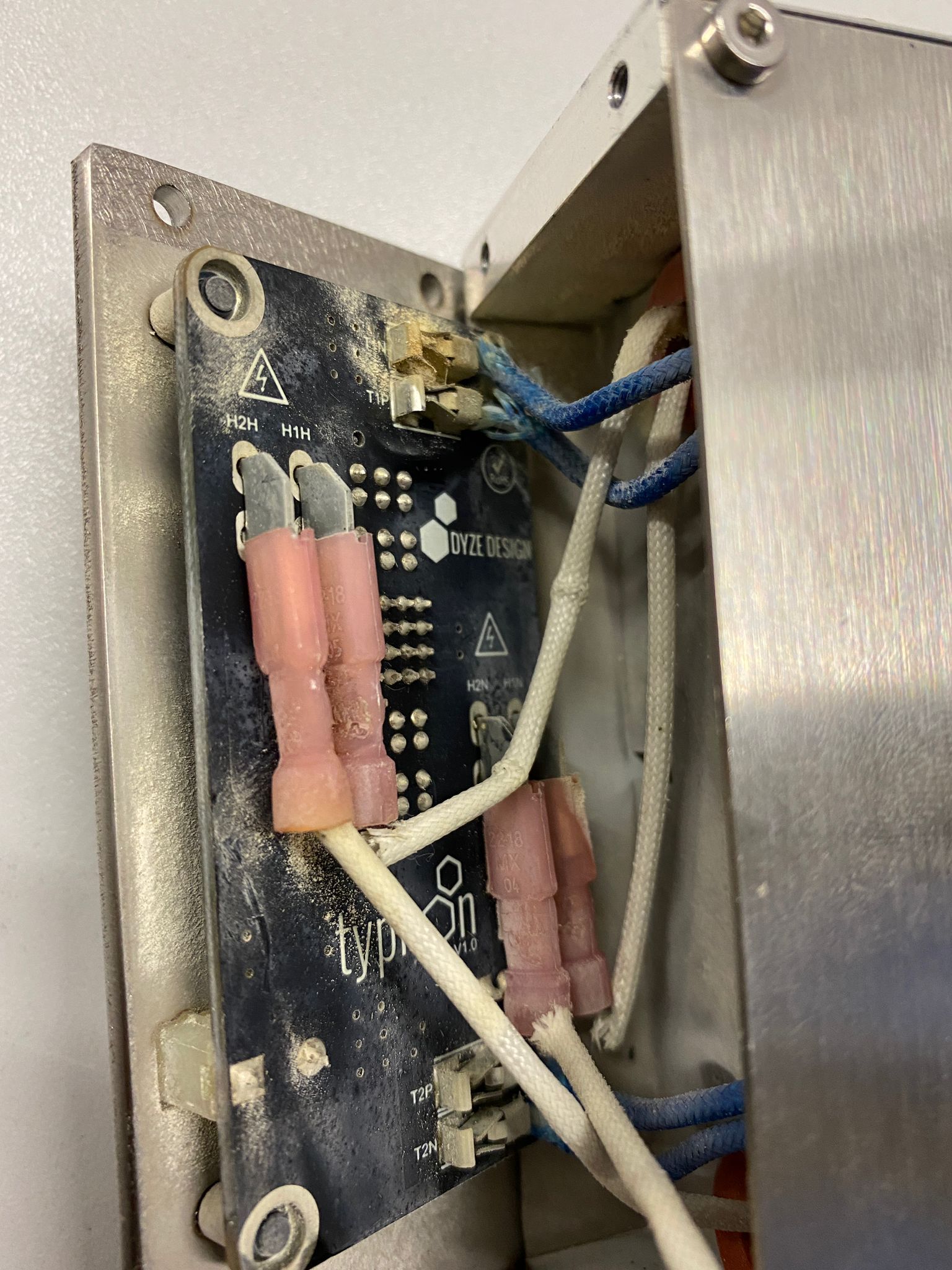
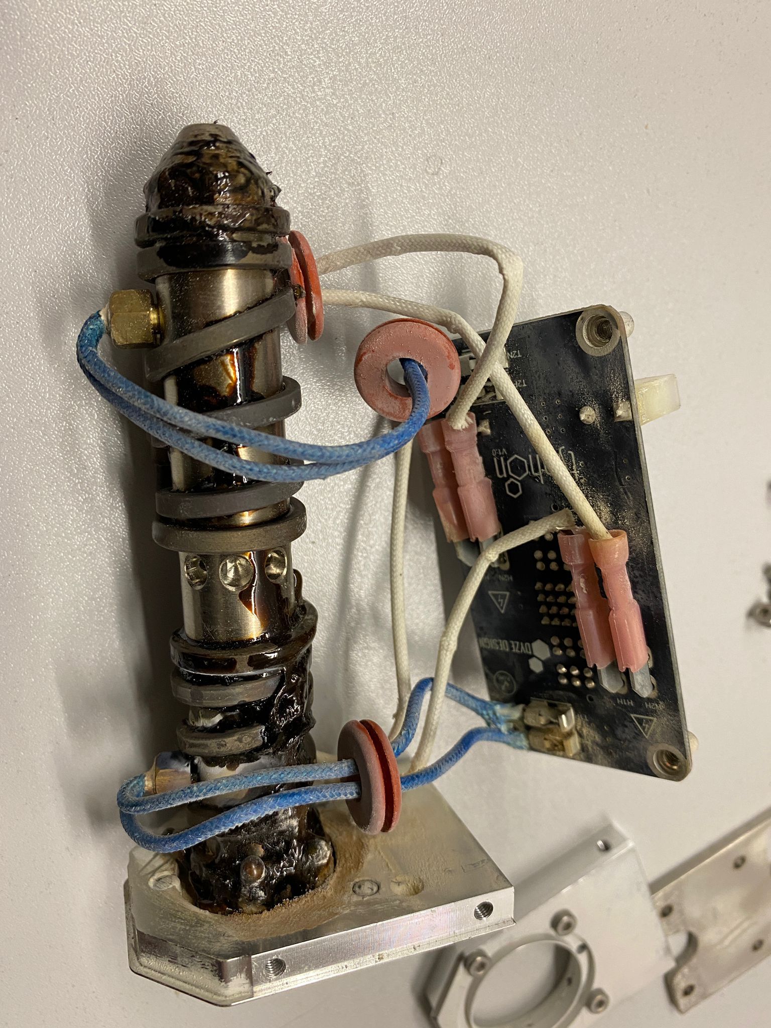
@phaedrux The damage is not really visible. But possibly weak connector clamping caused a weak spot on the wire to warm up. When I connect again and try again smoking! Therefore, the plastic insulation where below glass-fiber sleeves of resistant wiring seem burned away. But the glass-fiber sleeve is still in good condition. I have only seen ashes on connectors and heavy smoke dirtiness. It was flying while on disassembly, so I cleaned up a bit.
However, these hot-ends are designed above 400 celsius. Even the PWM 1.00, was not above 280 on the peak temperature for a few seconds. I don`t think something to todo with settings.
I regret now that I did not snap a photo before the ash cleanup
") but I will try to get better images to share tomorrow.
but I will try to get better images to share tomorrow. -
@sozkan I'm wondering if there is/was a bad joint somewhere - either a bad crimp contact or a poorly soldered connector. It would explain why you were getting seemingly intermittent faults. Using a low PWM value would have effectively reduced the current and prevented the arcing which then occurred when you raised the PWM value and which caused the overheating at the connector.
-
@deckingman said in Disabling Heater Fault:
@sozkan I'm wondering if there is/was a bad joint somewhere - either a bad crimp contact or a poorly soldered connector. It would explain why you were getting seemingly intermittent faults. Using a low PWM value would have effectively reduced the current and prevented the arcing which then occurred when you raised the PWM value and which caused the overheating at the connector.
Thank you for the follow-up. Sorry for the late reply, I was Covid-2 Positive.
here are some photos I have taken and a video: https://youtu.be/RfPiJUVuZdE.
It is well and durable built. But however, strangely there is some resin-like leakage. But I don't think that the fume source is the resin burn.


-
I have installed another new hotend smaller diameter,
However this time H1 could not be calibrated at all. It took 3-4 hours to see the failed result. I think this time is not a technical issue. Somehow H2 is seemed okay. But, M303 H1 S220 result with failure:Warning: heater behaviour was not consistent during tuning Warning: Auto tune of heater 1 failed due to bad curve fit (R=5.433 K=4.650:0.000 D=14.85)These autotune things seem not really effective in my case.
Any suggestion?
-
@sozkan said in Disabling Heater Fault:
These autotune things seem not really effective in my case.
Any suggestion?
Having seen those pictures, it is clear that the Dyze heater elements are unlike the usual cartridge heaters that the majority of people use. Perhaps there is some characteristic about their design which means the normal PID tuning algorithms will not work well. Have you contacted Dyze designs and asked them if they have any suggestions or recommendations?
-
@deckingman said in Disabling Heater Fault:
@sozkan said in Disabling Heater Fault:
These autotune things seem not really effective in my case.
Any suggestion?
Having seen those pictures, it is clear that the Dyze heater elements are unlike the usual cartridge heaters that the majority of people use. Perhaps there is some characteristic about their design which means the normal PID tuning algorithms will not work well. Have you contacted Dyze designs and asked them if they have any suggestions or recommendations?
Yes, clearly they say they don"t provide software support and suggested PID tunning and find a solution here!
However, I still believe there is another way to run. But, not a time-dependent algorithm. That's one of the problems! Since we have sensors and all advanced PWM things what's the point of PID tuning checking for death and uptime! Even the tuning was working on pause days when started printing failed. It is fact that plastics flow even act like cooling and ruin the PID tuning setup and safety margins start activates! It seems it is not seen on hobby-grade printers.
I start thinking to develop an external controller independent from the Duet hardware for this hotend. For that purpose, An extra Arduino controller, a new algorithm just for heater controlling purposes!
1- if the temperature of each individual heater is below the threshold, keep powering the heater until the cut-off threshold temp.
2- temperature start expands, it does not matter in 1 second or 100 seconds.
3- If the temperature rises more than expected, the decision for duty cycle or decrease the cut-off threshold temperature slightly. Which could be even real-time tuning!Isn't that possible with the present controller?
-
Isn't that possible with an algorithm to play for real-time tuning?
like measured time 5 seconds at present or during the printing:- Within the cut-in and cut-off, if more than 5 seconds simply duty cycle activates for longer duty until continues power.
- if heating is shorter than 5 seconds, the duty cycle lowers the power.
- If the temperature is out of the limit is due to the thermal expansions, lower the duty or cut-off thresholds.
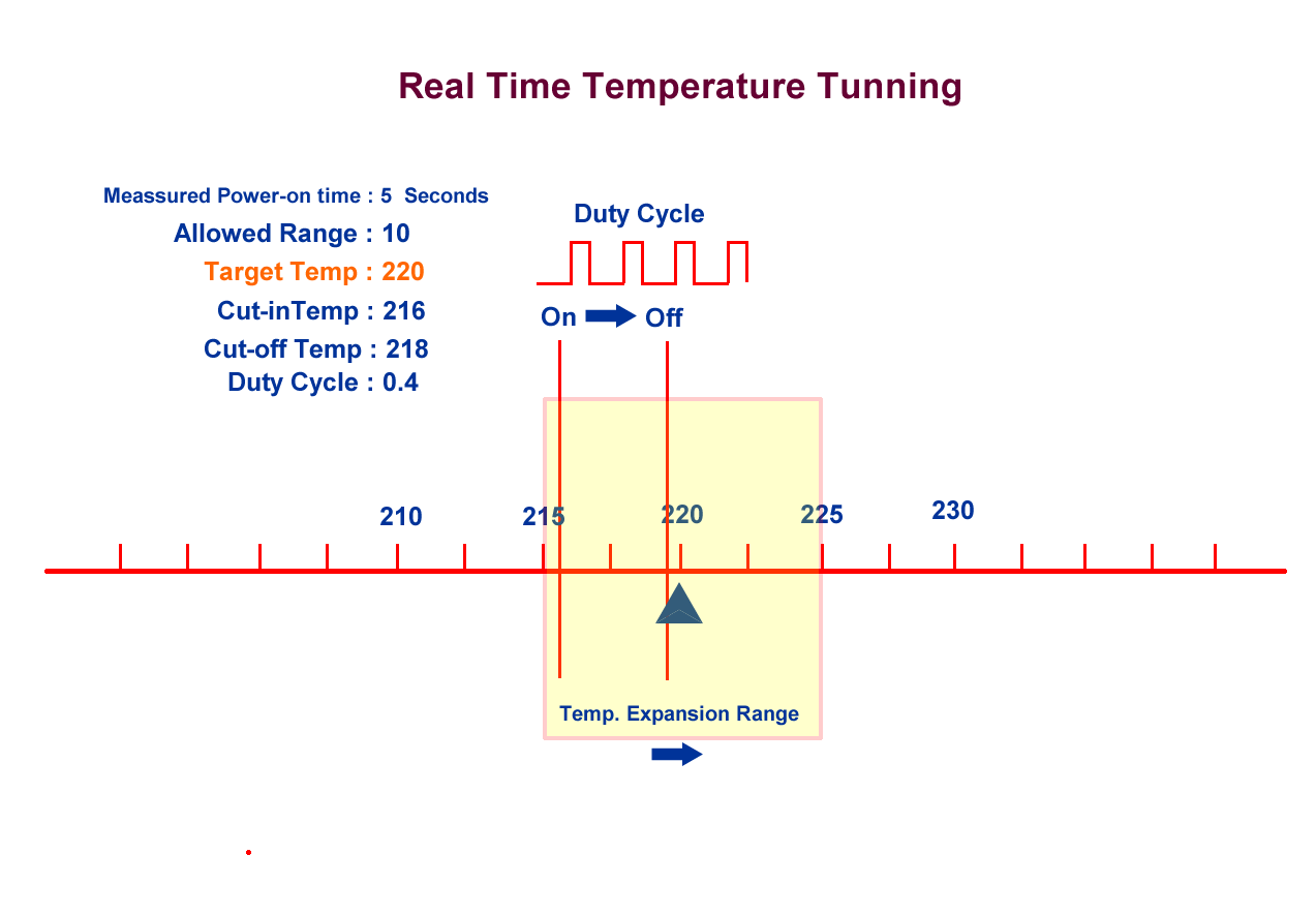
It seems simple and more functioning to me. Measured time is even completely unnecessary. if the temperature goes out of the limit, simply auto-decrease the duty cycle.
-
@sozkan What you describe is close to how bang-bang mode works. So you could try that instead of using PID (change the "B" parameter). It might be a better option for that particular hot end.
But IMO Dyze design are ducking their responsibilities by producing a device and not suggesting how to control it. The PID algorithm works fine for every other hot end - even those with multiple heaters ( as in my case using two heat zones, each with an 80 watt heater cartridge).
-
@deckingman said in Disabling Heater Fault:
@sozkan What you describe is close to how bang-bang mode works. So you could try that instead of using PID (change the "B" parameter). It might be a better option for that particular hot end.
But IMO Dyze design are ducking their responsibilities by producing a device and not suggesting how to control it. The PID algorithm works fine for every other hot end - even those with multiple heaters ( as in my case using two heat zones, each with an 80 watt heater cartridge).
Hi, thank you for the all suggestions. I am very grateful. I simply change to B1 and a bit play with PWM. Now it works much more stable. Thankfully, the problem is solved now.
By the way, the 2.5 mm of dyze hot end seems cracked due to my last year's hard start trial. They say the resin-like leakage seems like occurred from the crack. Therefore, they suggest for return for repair.
-
Hello All,
I just wanted to share the successful result:
The only target for me right now is filament detection. 5 kg filament consumed so fast
with no sense.