Part fan not starting after toolboard upgrade
-
I've just swapped to a V1.1 toolboard and for some reason my part cooling fan doesnt start.
The control slider on the web interface works, and I can control the fan with it during a print. I presume its something in the GCODE?
; Fans M950 F0 C"121.out2" Q80 ; create hotend fan 0 on pin toolboard out1 and set its frequency M106 P0 S0 H1 T45 C"Hotend Fan" ; set fan 0 value. Thermostatic control is turned on M950 F1 C"121.out1" Q250 ; create cooling fan 1 on pin toolboard out1 and set its frequency M106 P1 S0 H-1 B1 C"Part Cooling Fan" ; set fan 1 value. Thermostatic control is turned off -
@nick9one1 what's your M563 line in your config?
-
@jay_s_uk said in Part fan not starting after toolboard upgrade:
M563
; Tools
M563 P0 D0 H1 F0   					 			 ; define tool 0
G10 P0 X0 Y0 Z0 								 ; set tool 0 axis offsets
G10 P0 R0 S0 									 ; set initial tool 0 active and standby temperatures to 0C
;
M563 P1 D0 H1 F0 						  		 ; define tool 1
G10 P1 X0 Y0 Z0 								 ; set tool 1 axis offsets
G10 P1 R0 S0 									 ; set initial tool 1 active and standby temperatures to 0C
Should this be F1?
-
Which fan is physically where?
Right now you have fan0 defined as the hotend, and it's assigned as the part cooling fan for both tools.
Fan1 is defined as a part cooling fan, but assigned to neither tool.
-
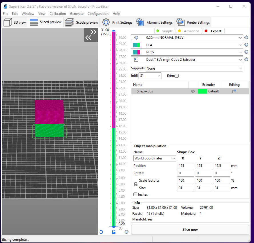
I only have one tool, but have two defined in the config so I can more easily do a filament type change in superslicer.
kind of like this;
going back to M563 - I must have swapped the fan wiring over when installing the new toolboard;
I've swapped F0 to be F1 and it seems to work
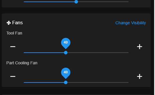
; Fans
M950 F0 C"121.out2" Q80                          ; create hotend fan 0 on pin toolboard out1 and set its frequency
M106 P0 S0 H1 T45 C"Hotend Fan"                  ; set fan 0 value. Thermostatic control is turned on
M950 F1 C"121.out1" Q250                         ; create cooling fan 1 on pin toolboard out1 and set its frequency
M106 P1 S0 H-1 B1 C"Part Cooling Fan"            ; set fan 1 value. Thermostatic control is turned off

; Tools
M563 P0 D0 H1 F1   					 			 ; define tool 0
G10 P0 X0 Y0 Z0 								 ; set tool 0 axis offsets
G10 P0 R0 S0 									 ; set initial tool 0 active and standby temperatures to 0C
;
M563 P1 D0 H1 F1 						  		 ; define tool 1
G10 P1 X0 Y0 Z0 								 ; set tool 1 axis offsets
G10 P1 R0 S0 									 ; set initial tool 1 active and standby temperatures to 0C
but what is slightly confusing is the two fans seem to be linked in the GUI.
If the print requires 100% fan speed both sliders move, then drop down to 40%
-
@nick9one1 said in Part fan not starting after toolboard upgrade:
but what is slightly confusing is the two fans seem to be linked in the GUI.
Tool fan is the part cooling fan of the currently selected tool. It makes more sense if you have multiple tools. So yes, they are linked, but it is only one fan.
It's usually a better idea to use fan0 as the part cooling fan for cases where the slicer is hard coded to target fan0.