Closed Loop - layer shift
-
hey
as @T3P3Tony suggest I opened a new thread to solve this closed loop issue.After PID tuning I have still layer shifts mostly on the x-axis.
May it´s something else..??
maybe CAN connection? It´s about 10 meters long and the X axis is on the board on the last place.
When I home X, the motor nozlle is in the rigth place again. Also when I manually stop the axis.I have the feeling, that changing the PID Term it´s getting better.
Would be nice if anybody has some suggestions for me.
Data from X axis
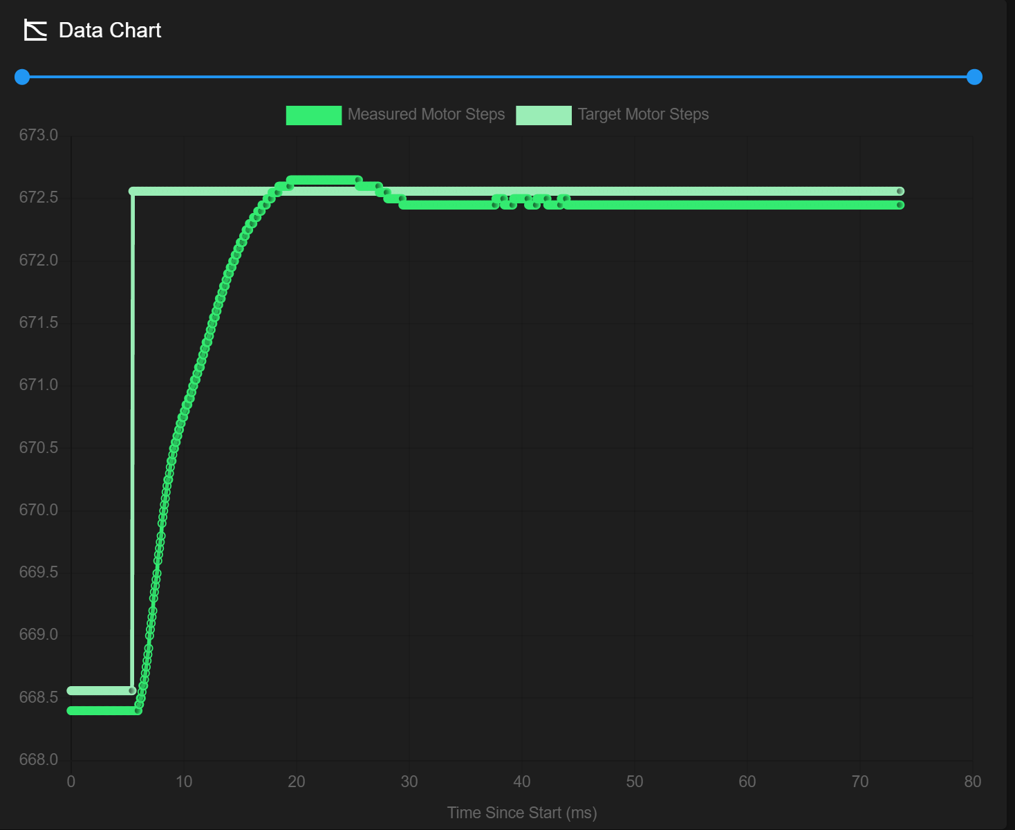
Maneuvre V31

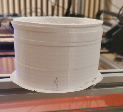
; Configuration file for Duet 3 (firmware version 3)
; executed by the firmware on start-up
;
; generated by RepRapFirmware Configuration Tool v3.2.3 on Mon Aug 02 2021 16:15:35 GMT+0200 (Mitteleuropäische Sommerzeit)

; General preferences
G90                                                        ; send absolute coordinates...
M83                                                        ; ...but relative extruder moves
M550 P"Duet 3"                                             ; set printer name

M552 s1

M587 S"AndroidAPebc3_EXT" P"hhhhhhhh"
G4 S4
M574 C1 S3
M574 C0 Z0
M915 P0.5 C S0 F0 R1

; Drives ;closed loop
M569.1 P20.0 T2 C5 R320 I0 D0 H70             ; Configure the 1HCL board at CAN address.20quadrature encoder 128 steps/motor full
M569.1 P21.0 T2 C5 R320 I0 D0 H70            ; Configure the 1HCL board at CAN address.21quadrature encoder 128 steps/motor full step.
M569.1 P22.0 T2 C5 R150 I0 D0 H70            ; Configure the 1HCL board at CAN address.21quadrature encoder 128 steps/motor full step.
M569 P20.0 D4 S1 ; Configure the motor on the 1HCL at can address 20 as being in closed-loop drive mode (D4) and not reversed (S1)
M569 P21.0 D4 S0 ; Configure the motor on the 1HCL at can address 21 as being in closed-loop drive mode (D4) and not reversed (S1)
M569 P22.0 D4 S1 ; Configure the motor on the 1HCL at can address 21 as being in closed-loop drive mode (D4) and not reversed (S1)

Other drives; open loop;
M569 P0.0 S1                                               ; physical drive 0.0 goes forwards
M569 P0.1 S1                                               ; physical drive 0.2 goes forwards
M569 P0.2 S1                                               ; physical drive 0.2 goes forwards
M569 P0.3 S1
M569 P0.5 S0
M569 P100.0 S0                                              ; physical drive 0.2 goes forwards
M584 X22.0 Y20.0:21.0 Z0.0:0.1:0.2:0.3 C0.5 E100.0                         ; set drive mapping
M350 X1 Y1 Z128 E16:16:16 I1                                         ; configure microstepping with interpolation
M92  X100.00 Y100.00 Z5120.00 C91.022 E409.00:409.00:409.00          ; set steps per mm
M566 X600.00 Y600.00 Z600.00 C3000 E600.00:600.00:600.00                    ; set maximum instantaneous speed changes (mm/min)
M203 X8000.00 Y8000.00 Z500.00 C10000 E6000.00:6000.00:6000.00          ; set maximum speeds (mm/min)
M201 X1300.00 Y1300.00 Z500.00 C400 E2500.00:2500.00:2500.00         ; set accelerations (mm/s^2)
M906 X1500 Y1300:1300 Z2300:2300:2300:2300 C400 E1000 I30                      ; set motor currents (mA) and motor idle factor in per cent
M84 S300                                                             ; Set idle timeout
M671 X-110:-110:1140:1140 Y-100:1140:1140:-110 S20 ; leadscrews at front left1 and n´back2. back rigth3 and front4

; Axis Limits
M208 X-10 Y0 Z0 S1                                      ; set axis minima
M208 X1000 Y890 Z850 S0                                  ; set axis maxima

; Endstops
M574 X2 S1 P"^22.io1.in"                                      ; configure active-high endstop for high end on X via pin ^io3.in
M574 Y2 S1 P"^20.io1.in+21.io1.in"                                      ; configure active-high endstop for high end on Y via pin ^io1.in

; Z probe
M558 P5 C"0.io1.in" H8 F2000 I0 T5000 	; Set Z probe type to switch, the axes for which it is used and the dive height + speeds
G31 P200 X5 Y30 Z0	 				    ; Set Z probe trigger value, offset and trigger height; Z probe
M556 S50 X0 Y0 Z0                                         ; set orthogonal axis compensation parameters
M557 X50:800 Y50:800 S37.5                             ; define mesh grid


; Heaters
M308 S1 P"100.temp0" Y"thermistor" T100000 B4138            ; configure sensor 1 as PT1000 on pin 121.temp0
M950 H1 C"100.out0" T1                                         ; create nozzle heater output on out1 and map it to sensor 1
M307 H1 B0 R1.553 C487.8 D10.35 S1.00 V0                   ; disable bang-bang mode for heater  and set PWM limit
M143 H1 S250                                               ; set temperature limit for heater 1 to 250C


M308 S0 P"temp0" Y"thermistor" T100000 B4138               ; configure sensor 0 as thermistor on pin temp0
M950 H0 C"out0" T0                                         ; create bed heater output on out0 and map it to sensor 0
M307 H0 B0 R0.243 C586.2 D33.87 S1.00 V0                   ; disable bang-bang mode for the bed heater and set PWM limit
M140 H0
M143 H0 S120

; Fans
M950 F0 C"100.out1" Q500                                   ; create fan 0 on pin 121.out1 and set its frequency
M106 P0 S0 H-1                                             ; set fan 0 value. Thermostatic control is turned off
M563 P0 D0 H1                                              ; tool uses extruder 0, heater 1
M950 F1 C"100.out2" Q500                                   ; create fan 1 on pin 121.out2 and set its frequency
M106 P1 S1 H1 T45                                          ; set fan 1 value. Thermostatic control is turned on
M563 P0 D0 H1 F1                                           ; tool uses extruder 0, heater 1
M950 F2 C"3.out1" Q500                                    ; create fan 2 on pin 122.out1 and set its frequency
M106 P2 S1 H-1                                             ; set fan 2 value. Thermostatic control is turned off
M950 F3 C"3.out2" Q500                                    ; create fan 3 on pin 122.out2 and set its frequency
M106 P3 S1 H2 T45                                          ; set fan 3 value. Thermostatic control is turned on
M950 F4 C"out1" Q500                                   ; create fan 4 on pin 123.out1 and set its frequency
M106 P4 S1 H-1                                             ; set fan 4 value. Thermostatic control is turned off
M950 F5 C".out2" Q500                                   ; create fan 5 on pin 123.out2 and set its frequency
M106 P5 S1 H3                                           ; set fan 5 value. Thermostatic control is turned on
M950 F6 C"2.out6" Q500                                       ; create fan 6 on pin out4 and set its frequency
M106 P6 S0 H-1                                             ; set fan 6 value. Thermostatic control is turned off
M950 F7 C"2.out7" Q500                                       ; create fan 7 on pin out5 and set its frequency
M106 P7 S0 H                                            ; set fan 7 value. Thermostatic control is turned on
M950 F8 C"2.out8" Q500 CMagnet0                              ; create magnet 0  on pin out9 and set its frequency
M106 P0 S0 H-1                                             ; set fan 0 value. Thermostatic control is turned off
M950 F9 C"1.out6" Q500 CMagnet1                              ; create magnet 0  on pin out9 and set its frequency
M106 P0 S0 H-1                                             ; set fan 0 value. Thermostatic control is turned off
M950 F10 C"1.out6" Q500 CMagnet2                           ; create magnet 0  on pin out9 and set its frequency
M106 P0 S0 H-1                                             ; set fan 0 value. Thermostatic control is turned off
M950 F11 C"out7" Q500 CMagnet3                           ; create magnet 0  on pin out9 and set its frequency
M106 P0 S0 H-1                                             ; set fan 0 value. Thermostatic control is turned off

; Tools
M563 P0 D0 H1 F0                                           ; define tool 0
G10 P0 R0 S0                                               ; set initial tool 0 active and standby temperatures to 0C


; Custom settings are not defined

; Miscellaneous
M911 S10 R11 P"M913 X0 Y0 G91 M83 G1 Z3 E-5 F1000"         ; set voltage thresholds and actions to run on power loss
Picture below: first layer shift (x) was done by the printer. Second shift was after homing to bring it back to the rigth position.
Picture below: some shift before tuning PID. But I´m not sure if this an PID issue.
thanks a lot
Richard -
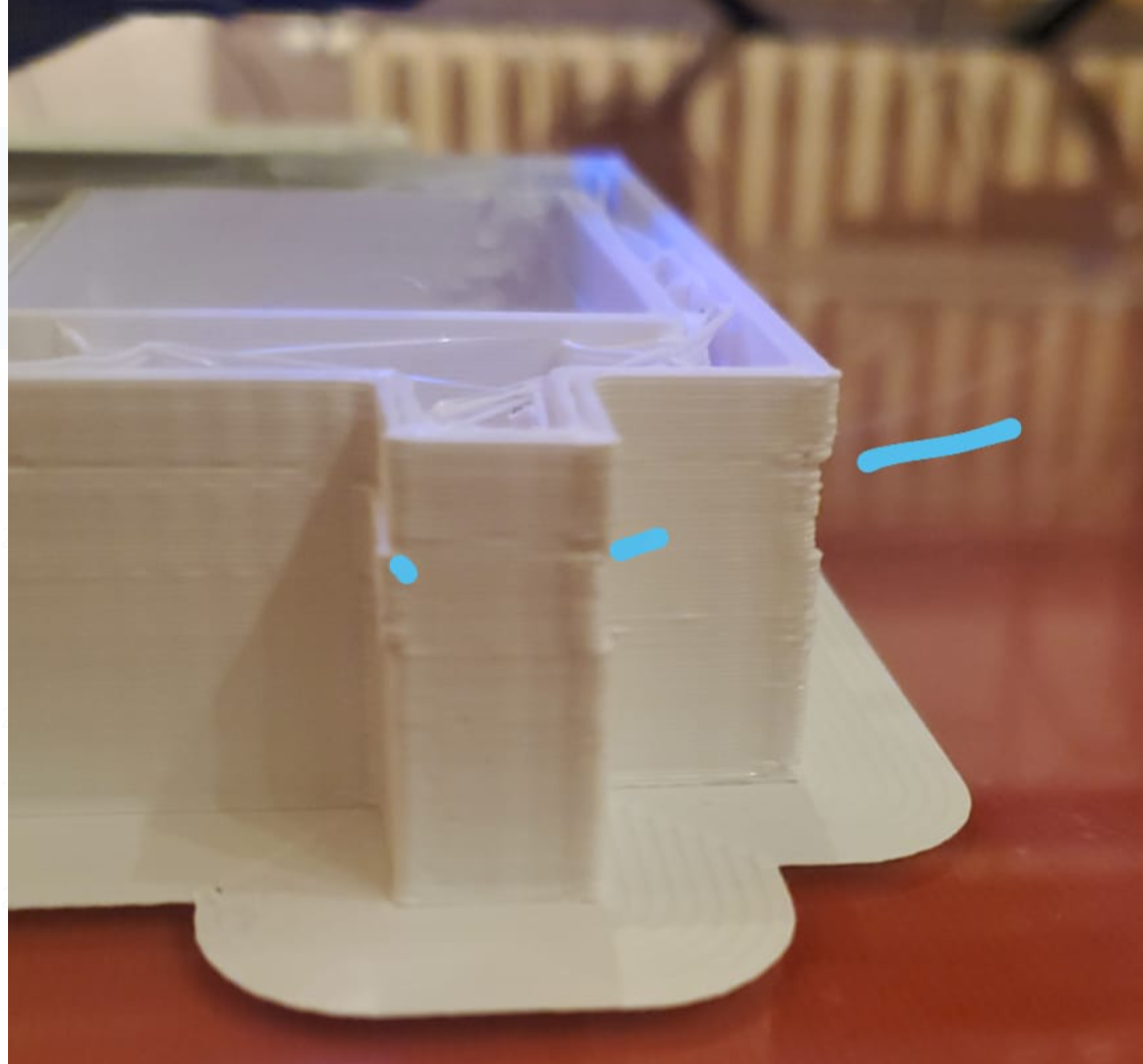
layer shift happened may when loosing connection -->
correct themself after 4 min and was printing on fine. Pictures follow
-
@gruna-studio
Those layer shifts are MASSIVE.
There's no way they are caused by tuning the PID loops.
Either your encoder wiring is not secure or there's a firmware problem that's causing loss of encoder counts.
- How do you have the encoder wires routed? Near the stepper motor wiring?
- How sure are you that the crimps (and solder) are good on the connectors?
SeemeCNC Rostock Max V3 converted to V3.2 with a Duet2 Ethernet Firmware 3.2 and SE300
-
So the shifts are still on the x axis, but less and much smaller. Y axis is fine now.
Encoder wiring is far away from stepper wiring. Turns directly in a different way etc...
I´m relativ sure about the soldering. I mean I had also shifts in the Y-Axis and they´re gone after a bit of tuning etc.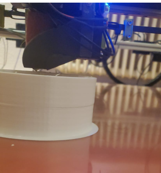
thanks richard -
@alankilian
edit
at the moment I wrote that the Y-Axis has no shift anymore, it happened again. Same shift sice then X shift before.
The DWC shoes sometimes only 23.2V. Is that normal?
Edit2.0
When I turn off my repeater source wifi and reconnect, that gives a new Ip adress (at the moment) to the Duet, the layer shift will happen. The faster the printer prints at the moment, the bigger the shift. I´m pretty sure.
I do some more testing and will write later on, too.
-
Can connection theory is dead.
Any other Idea?
Overheating ?
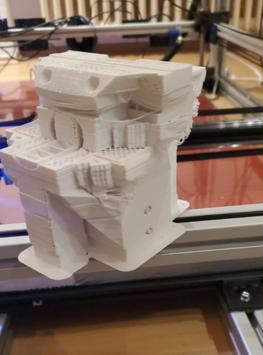
I don´t know. That does´nt make fun.PIcture:
2 hour print
No y shift
several x shifts.