Backlash? Step rounding error? Weird repeatability issue.
-
Just finished building a new custom printer and seem to be having what I would normally say is backlash, but I've generally ruled out all the normal culprits. Grub screws on pulleys are tight, belts are tensioned, belt mounts to the carriage are solid, I'm even using genuine gates belts (9mm GT2) and pulleys.
But I still have a ~0.1mm repeatability issue on the X axis. Noticed when trying to use a USB microscope to calibrate the offset between my two tools (it's IDEX). I know this is more hardware than Duet specific, but I feel like I've ruled out all the normal stuff and it's got me partially wondering if it's firmware? Not sure how, floating point inaccuracy and rounding can be a pain sometimes, so who knows. I've seen weirder things.
I captured a video demonstrating what I mean, see below.
Any thoughts greatly appreciated.
System info:
Board: Duet 3 MB6HC (MB6HC) DSF Version: 3.4-rc2 Firmware: RepRapFirmware for Duet 3 MB6HC 3.4.0rc2+2 (2022-03-07) config.g
; Configuration file for Duet 3 (firmware version 3.3) ; executed by the firmware on start-up ; ; generated by RepRapFirmware Configuration Tool v3.3.10 on Mon Feb 14 2022 00:04:10 GMT-0500 (Eastern Standard Time) ; General preferences G90 ; send absolute coordinates... M83 ; ...but relative extruder moves M550 P"Rancor" ; set printer name ; Audio Player Serial Config M575 P2 B57600 S2 ; Setup UART on IO_1 to 57600 baud ; Setup Lights M950 P0 C"0.out9" Q4000 ; Wait a moment for the CAN expansion boards to start G4 S2 ; Drives M569 P0.0 S0 ; Left Y M569 P0.1 S1 ; Left X M569 P0.2 S0 ; Left Extruder M569 P0.3 S1 ; Left Z M569 P0.4 S1 ; Right Rear Z M569 P0.5 S1 ; Right Front Z M569 P1.0 S1 ; Right Y M569 P1.1 S1 ; Right X M569 P1.2 S0 ; Right Extruder M584 X0.1 U1.1 Y0.0:1.0 Z0.3:0.4:0.5 E0.2:1.2 ; set drive mapping M350 X16 U16 Y16 Z16 E16:16 I1 ; configure microstepping with interpolation M92 X160 U160 Y160 Z1600 E397:397 ; set steps per mm M566 X400 U400 Y400 Z100 E1500:1500 ; set maximum instantaneous speed changes (mm/min) M203 X15000 U15000 Y15000 Z900 E3600:3600 ; set maximum speeds (mm/min) M201 X750 U750 Y750 Z100 E1500 ; set accelerations (mm/s^2) M906 X1400 U1400 Y1400 Z1200 E1100:1100 I75 ; set motor currents (mA) and motor idle factor in per cent ;M84 S30 ; Set idle timeout ;Leadscrew locations M671 X-13.7:343.8:343.8 Y160:287.5:32.5 S7.5 ; Axis Limits ; TODO - these are wild guesses at this point for X ; will need to change mins to negatives M208 S1 X-85 U0 Y0 Z-2 ; set axis minima M208 S0 X405 U450 Y345 Z600 ; set axis maxima ; Endstops M574 X1 S1 P"0.io2.in" ; X homes low end M574 U2 S1 P"1.io2.in" ; U homes high end M574 Y1 S1 P"0.io3.in+1.io3.in" ; Y has dual motors and endstops ; TODO - setup homing files https://duet3d.dozuki.com/Wiki/ConfiguringMultipleIndependentXcarriagesCartesian#Section_Homing_files ; Z-Probe M558 P5 C"^0.io5.in" H2.5 F250 T6000 ; set Z probe type to switch and the dive height + speeds G31 P500 X0 Y0 Z0.1 ; set Z probe trigger value, offset and trigger height M557 X15:315 Y20:300 S75:70 ; define mesh grid ; Heaters ; Bed M308 S0 P"0.temp0" Y"thermistor" T100000 B4240 ; configure sensor 0 as thermistor on pin temp0 M950 H0 C"0.out0" T0 ; create bed heater output on out0 and map it to sensor 0 M307 H0 B0 R0.611 C647.0 D2.25 S1.00 ; enable bang-bang mode for the bed heater and set PWM limit M140 H0 ; map heated bed to heater 0 M143 H0 S120 ; set temperature limit for heater 0 to 120C ; Left M308 S1 P"0.temp1" Y"thermistor" T100000 B4725 C7.06e-8 ; configure sensor 1 as thermistor on pin temp1 M950 H1 C"0.out1" T1 ; create nozzle heater output on out1 and map it to sensor 1 M307 H1 R2.616 K0.237:0.348 D5.69 E1.35 S1.00 B0 V23.9 ; disable bang-bang mode for heater and set PWM limit M143 H1 S285 ; set temperature limit for heater 1 to 280C ; Right M308 S2 P"1.temp0" Y"thermistor" T100000 B4725 C7.06e-8 ; configure sensor 2 as thermistor on pin 1.temp0 M950 H2 C"1.out0" T2 ; create nozzle heater output on 1.out0 and map it to sensor 2 M307 H1 R2.616 K0.237:0.348 D5.69 E1.35 S1.00 B0 V23.9 ; disable bang-bang mode for heater and set PWM limit M143 H2 S285 ; set temperature limit for heater 2 to 280C ; Fans ; left HEF M950 F0 C"0.out7" ; create fan 0 on pin out7 and set its frequency M106 P0 S1 H1 T45 ; set fan 0 value. Thermostatic control is turned on ; Left PCF M950 F1 C"0.out8" ; create fan 1 on pin out8 and set its frequency M106 P1 S0 H-1 ; set fan 1 value. Thermostatic control is turned off ; Right HEF M950 F2 C"1.out7" ; create fan 2 on pin 1.out7 and set its frequency M106 P2 S1 H2 T45 ; set fan 2 value. Thermostatic control is turned on ; Right PCF M950 F3 C"1.out8" ; create fan 3 on pin 1.out8 and set its frequency M106 P3 S0 H-1 ; set fan 3 value. Thermostatic control is turned on ; Tools ; Left M563 P0 S"Left" D0 X0 H1 F1 ; define tool 0 G10 P0 X-71.5 Y-20.6 Z1 ; set tool 0 axis offsets G10 P0 R0 S0 ; set initial tool 0 active and standby temperatures to 0C ; Right M563 P1 S"Right" D1 X3 H2 F3 ; define tool 1 G10 P1 X0 Y-20.6 Z0 ; set tool 1 axis offsets G10 P1 R0 S0 ; set initial tool 1 active and standby temperatures to 0C ; Custom settings are not defined ; Miscellaneous T0 P0 ; select first tool -
Two possibilities I can think of:
A very slight rocking or tilting on the head carriage, so the target point changes even though the belt position is the same.
Or, just friction and fundamental stepper drive limitations.
A stepper motor has zero torque when exactly in its theoretical target position; the torque increases rapidly as it's held away from that point.
As the load moves in to position, at some distance from the theoretical target the frictional load will exceed the decreasing torque and cause a tiny position error, depending on the direction of movement and friction vs motor capabilities.
And to make that worse, microstepping "steps" have far less torque capability compared to full steps, where the motor poles are in mechanical alignment.
More info:
https://www.raynetrepair.us/electric-motors/step-position-error-and-holding-torque.htmlhttps://www.machinedesign.com/archive/article/21812154/microstepping-myths
-
Just and additional thought
I would put the microscope so you can see if the belt is repeatable this will rule out backlash. it is is not repeatbable do the same with the motor to see if that is repeatable. I do know if you are stopping on a microstep this may not be repeatable -
@rjenkinsgb said in Backlash? Step rounding error? Weird repeatability issue.:
A very slight rocking or tilting on the head carriage, so the target point changes even though the belt position is the same.
@percar said in Backlash? Step rounding error? Weird repeatability issue.:
I would put the microscope so you can see if the belt is repeatable
Thanks for the suggestions!
I put the microscope on the belt and, sure enough, it's dead on repeatable - zero slop.Now, I don't feel any tilting in the carriage but at least I know it's not in the belts now.
Much more to go on.
Thanks! -
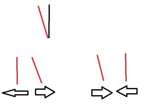
@adammhaile I find it very confusing that the result of moving left-right is different from the result of right-left. I thought about it and two ideas are
- microscope tilting by the movement to one side. The one direction combination tilts it, the other also, but is corrected by the second movement part
- axis inside stepper has play (inside a stepper are two ball bearings), and at one direction more than to the other. Or stepper holder can rotate a bit in one direction
black is the expected position, and it can tilt like the red. Then left-right is different from right-left (tilting by the movement accel):
For finding out the reason, you can apply a spring to the microscopy/stepper so it is held at one position. Or when the movement stopped at the "wrong position", touch with a finger and test whether it has play between this position and the correct one, so it can be moved between the two positions with very low force.
You mentioned as first thought it may be a firmware problem. The wrong movement is later corrected by the opposite directions, so the error would be temporary. You can test that by running M114 at all positions and check whether the first count value (this is the absolute X value *)) is the same for the left-right and the right-left movements.
*) the starting value is set by homing and then by every movement. The value change is steps * microsteps (* gear ratio) / belt movement by one rotation, so in case you use 400-step steppers, 20 teeth (40 mm) and 16 microsteps, for every mm movement it is 400*16/40 value change (the M92 value).
-
Another thing to check: I have a high resolution camera in my system also. It was a surprise to me to find out how little force on the camera module caused significant change in the image position, which looked like backlash in the machine. Lesson: The camera cable needs to be fixed to the machine really solid, so that when machine moves and the cable bends, it doesn’t transfer any force to the camera itself.