1LC IO Failure
-
Hello!
I know this is probably a very basic question, but this is my first time using a Duet expansion board, so I'm unsure what the expected behavior is or if I'm making a simple mistake.
My 1LC board appears to be powered and connected to my Duet 5 (via CAN) to my main board correctly (M115 B121 returns "Duet TOOL1LC firmware version 3.3")
I'm trying to control individual IOs, so I would expect the following to set the out0 high. However, I'm not seeing any change in output voltage (same results with out1 and out2).
M950 P0 C"121.out0"
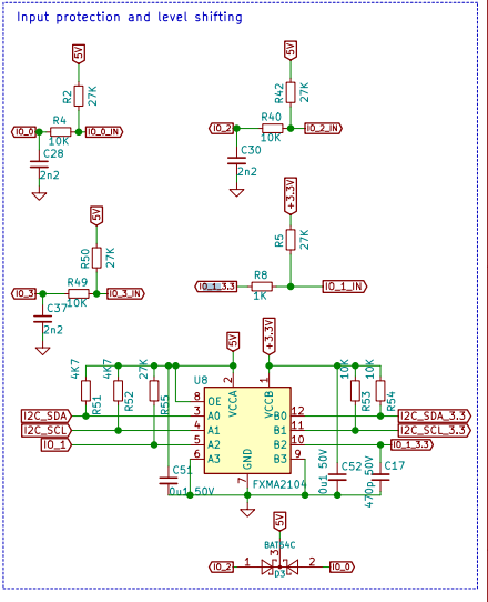
M42 P0 S1I'm also measuring 5V at all the inputs (io0.in, io1.in, io2.in) but as far as I can tell, there's no pull up resistor on these inputs.
Am I doing something incorrectly?
-
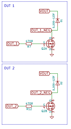
I don't know how you would figure this out from the documentation, but OUT1 and OUT2 are high-current outputs that can only sink current and cannot source it so you won't see a voltage between OUT1 and ground unless there's something connected between OUT1 and some power source.
If you connect a resistor, heater, fan or something like that between OUT1 and +VOUT, THEN you'll see a voltage at OUT1 (when the device is turned OFF) and you'll see 0 Volts when the device is turned on.
It seems confusing, but there's science behind this.
Also, there are pullups on the IO pins.
-
@alankilian Thank you! Got those IOs working now that I have a fan wired-up!
-
@georgiad AWESOME!!!