Configure GPIO input on Toolboard
-
I'm trying to hook up Toolboard docked detection using the microswitch on the Toolboard (v1.1)
I've set it up my first tool as CAN address 100.
I can see the sync LED blinking as it's suppose to, and I can read the temperature.
So, connection issues shouldn't be the problem here.I'm Trying to hook the endstop input to a IO slot to read it out later.
in the config.g I have:
M950 J1 C"^100.io3.in"As per my understanding I should be able to see the state change in the object model plugin under sensors->gpIn->1->value.
This is constantly '1'.
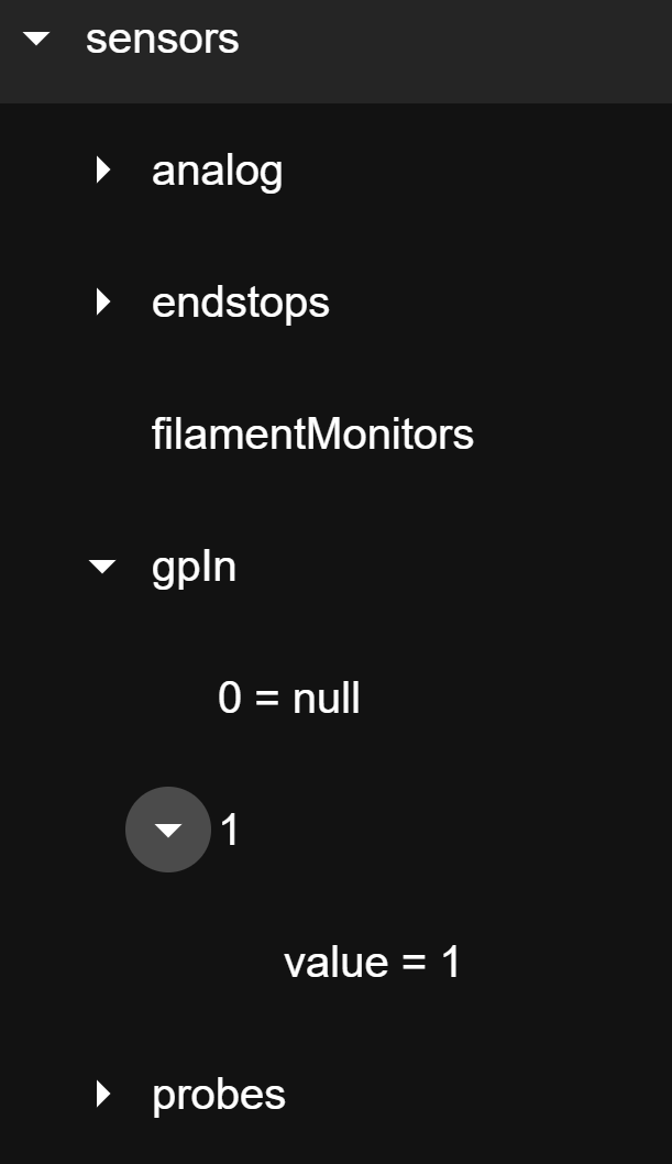
This parameters in the disappears form the object model plugin, when I comment out the config line, So it must have something to do with it...
Any pointers in what I'm doing wrong, or how I could make this easier/better?
-
How do you have the microswitch hooked up?
-
@alankilian I've soldered it to the designated pins on the Toolboard (IO3).
But your input was probably enough to solve this issue. I use the switch fliped on its Head (sensor arm pointing down) so the common pin on the switch is now connected to NC.
Off course that's not gonna work.
Nothing a bridging wire can't solve...
I will report back in the evening.Thanks for the input.
-
Allright, bridging the Top Pin (NC on the PCB) to the bottom one (io3.in) did the trick.
I had to invert the signal but other than that no changes were necessary on my firmware configuration.
For future reference and anyone who is trying to do something similar:
M950 J1 C"!^100.io3.in" ; Tool1 docking detection GPIO setupIs the command I use now.