Fusion 360 CNC and laser post processors with tool workflow
-
Hello all,
I thought I'd provide a workflow for those interested in using Fusion 360 for CNC and laser work. Hopefully it's useful.
I'm running RRFW 3.3 on a Duet 3 running 32v for motors and 24v for most everything else. I'll cover how I build a tool library in Fusion 360 and call macros for a manual tool change between operations with a modified post processor for a pwm controlled spindle and a stationary z probe. I've also enabled arcs in this post processor.

First setup your tool library in Fusion 360 including data on spindle speeds and feedrates.
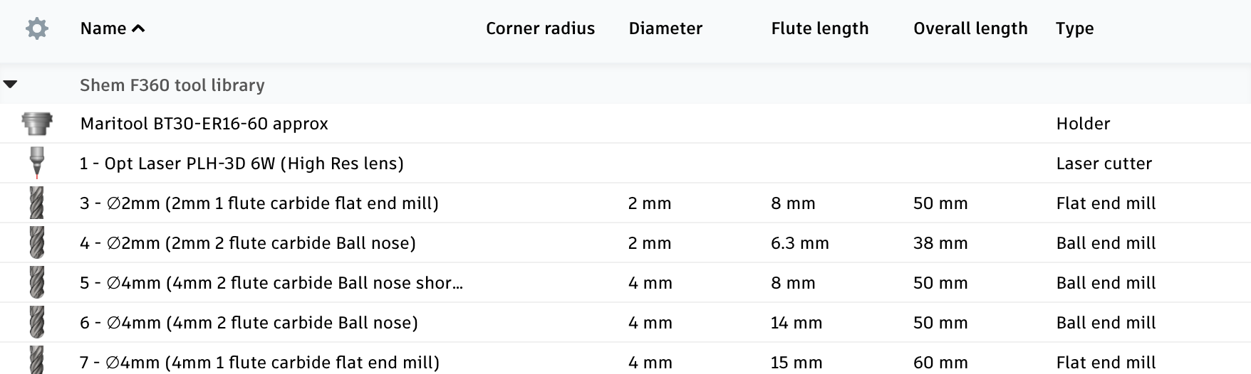
I reserve T1-T2 for defining tools such as spindles and laser engravers in my config files. Using T0 has caused me issues, so I avoid using that. Use T3 and above in Fusion 360 for defining bits. Note: a new tool will default to the lowest available number so make sure you add it to the bottom of the list. Save to the cloud tool library (preferences -> manufacture -> enable cloud libraries).
In my config.g file, I have as many Tx as I have bits in my library.
; Tools
; No tool is selected at startup
M453						                ; Set to CNC mode,
M950 R0 C"out0+out6" Q300 L0:24000          ; Select Spindle On/Off,RPM & Direction (not selected).
M563 P1 S"Laser"					; Create tool 1 Laser
M563 P2 S"Spindle" R0				; Create tool 2 with Spindle

; Create enough tools to cover library of F360 CAM tools and link to R0
M563 P3 S"T3" R0
M563 P4 S"T4" R0
M563 P5 S"T5" R0
M563 P6 S"T6" R0
M563 P7 S"T7" R0
M563 P8 S"T8" R0
M563 P9 S"T9" R0
M563 P10 S"T10" R0

; PWM Laser Enable 1# 2
M950 P1 C"io4.out"                      ; Use C"" for output - Opt Lasers enable input #1
M42 P1 S0				                    ; Ensure P1 is off - enable input #1
Your CAM will show the tool numbers:
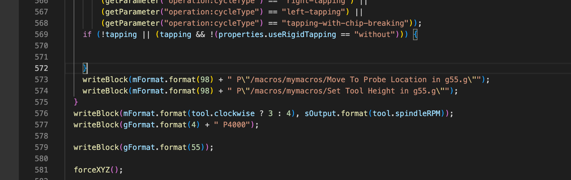
Upload the post processor I have provided. The post processor will call for a tool change if required. It does this by calling on macros I have also provided here. If you want to run a different macro, simply open up the post processor in Visual Studio Code and change the file path at LINE 573, save, and reupload to F360.
For the macros, these were written mostly by @EducatingSavvas for his moot line of CNC machines. I'll provide a workflow here as well as I think it's helpful.
Again, my machine has a fixed z probe button just off the work area. macros 01-04 are for initial setup of the machine. 02 and 04 need to be changed when resurfacing the waste board
01 - Set Probe Location
first sets the location of the probe and permanently stores this info02 - Set Probe to Waste Board Distance G55
Then stores the difference between the probe and the waste board.03 - Set X Y Datum In g55
This sets the location of my machine X0 Y0 work coordinates04 - Set X Y Z Datum in g56 for laser
I have a laser attached next to the spindle (magnetically removable optlaser). I use this macro to set the offset in X, Y, and Z. U simply make a mark with my CNC vbit in g55 at X0 Y0 then jog the laser over to the same spot and then use this macro for setting laser X0 Y0 and Z0 in g56. This means that the spindle and the laser are perfectly aligned.These next macros are called in the gcode during a tool change:
Move To Probe Location in g55
moves the spindle to the Z probeSet Tool Height in g55
adjusts new tool to wasteboard Z0That's all there is to it.
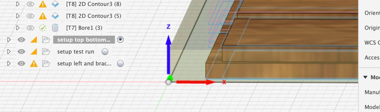
In F360, select the bottom of the stock for your origin point and this will correspond to Z0, the top of your waste board.
I have also include Tpre, Tpost, and probe files for good measure.
I keep getting a parse error when trying to upload files. I will try to post the files in a second thread.
-
Ok, here are the CNC and laser post processors. I have also included a sample output gcode from the CNC post processor. sample CNC PP gcode.gcode F360 Laser Duet PP.cps F360 Duet CNC PP.cps
-
Here are the macros. Place them in a folder called mymacros
@sdj Set Tool Height in g55.g Move To Probe Location in g55.g 04 - Set X Y Z Datum in g56 for laser.g 03 - Set X Y Datum In g55.g 02 - Set Probe to Waste Board Distance G55.g 01 - Set Probe Location.g
-
-
 undefined djthuma referenced this topic
-
 undefined T3P3Tony referenced this topic
-
undefined T3P3Tony referenced this topic